Controls, Start-Up, Operation, Service and Troubleshooting
CONTENTS
Enable-Off-Remote Contact Switch SW1
Touch Pilot Operation Configuration Tables
SAFETY CONSIDERATIONS
CONTENTS cont
CONFIGURATION FOR i-Vu DEVICE AND CSM CONTROLLER
START-UP CHECKLIST
Display Module Usage
GENERAL
Staged Loading Sequence = 1, LLCS = Circuit A leads
Fig. 1 - Touch Pilot Display
Fig. 2 - Group Display Screen a30-4910.ep
PDS-XAXQXW
Fig. 3 - Point Data Dialog Box a30-4471
Fig. 4 - Main Menu Display a30-4472
a30-4829
Fig. 5 - Touch Pilot Display Menu Structure
a30-4474
Fig. 6 - Setup Menu Display
Table 1 - Setup Menu
To change the Time and Date, press the Main Menu
Fig. 7 - Navigator Display Module
Fig. 8 - Main Base Board
CONTROLS
Table 2 - ComfortLink Navigator Display Menu Structure
Circuit B Discharge
Table 3 - Main Base Board Inputs and Outputs
Dual Chiller
Dual Set Point Input
a30-4215
Table 4 - DIP Switch 1 S1 Inputs
Fig. 9 - Compressor Protection Module
Table 5 - Compressor Protection Module Inputs and Outputs
Fig. 10 - EXV Board
Electronic Expansion Valve EXV Board
SGTA
Table 6 - EXV1 Board Inputs and Outputs 30XW150-325
Table 7 - EXV1,2 Board Inputs and Outputs* 30XW350,400
0-10 VDC
Table 8 - Auxiliary Board Outputs
Fig. 12 - Energy Management Module
Enable-Off-Remote Contact Switch SW1
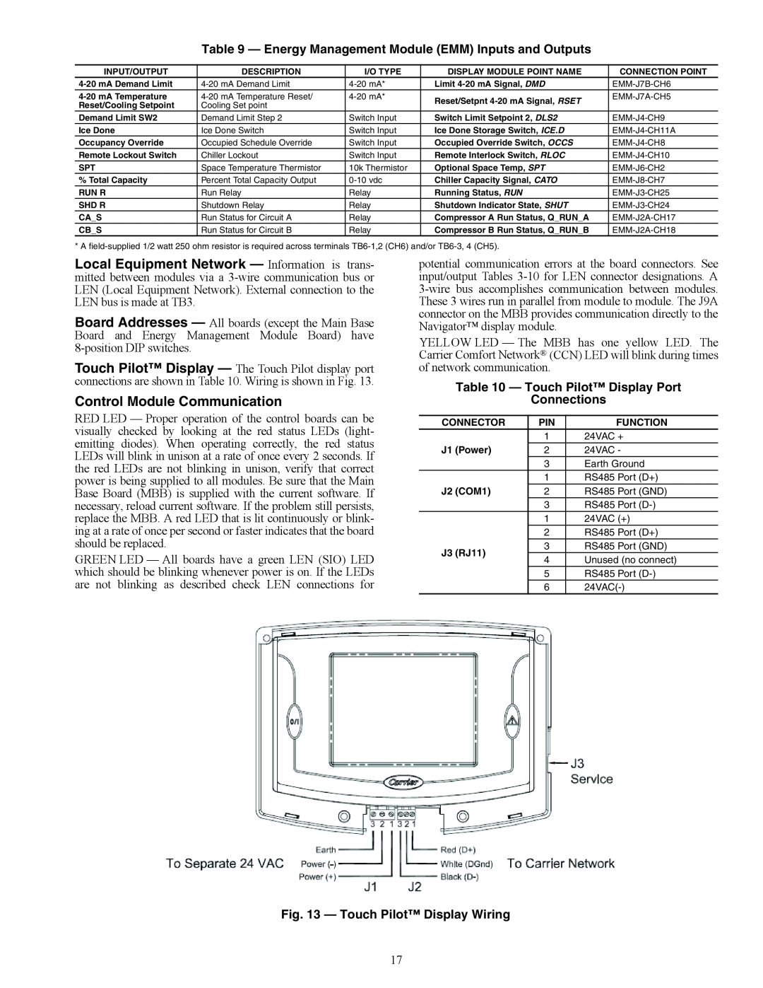
Fig. 13 - Touch Pilot Display Wiring
Control Module Communication
Table 9 - Energy Management Module EMM Inputs and Outputs
Table 10 - Touch Pilot Display Port Connections
Carrier Comfort Network CCN Interface
CONFIGURATION
Table 11 - CCN Communication Bus Wiring
Fig. 14 - ComfortLink CCN Communication Wiring
Broadcast address processing list secondary
Table 12 - Touch Pilot Controller Identification Configuration Table
Table 13 - Touch Pilot User Configuration USERCONF Table
Fig. 15 - Equipment Start Screen
Table 14 - Touch Pilot Start/Stop Control
Fig. 16 - Chiller Schedule Screen
Table 15 - Configuring the Schedule with Touch Pilot Display
Table 16 - Programming Holiday Schedules with Touch Pilot Display
Timed Override
Fig. 17 - Equipment Stop Screen
SWITCH
Table 17 - Navigator Start/Stop Control
Operating Control
Table 19 - Configuring Holiday Schedules for Navigator Display
Table 18 - Configuring Schedules with Navigator Display
Clock→ HOLI→ HOL.1
Clock→ HOLI→ HOL.2
Table 20B - Cooling Set Point Selection with Navigator Display
Table 21 - Configuration Set Point Limits
Table 20A - Cooling Set Point Selection with Touch Pilot Display
Table 23 - Cooling Set Point Selection Navigator Parameters
Table 22 - Cooling Set Point Selection Touch Pilot Parameters
Fig. 18 - 4 to 20 mA Set Point Control
To configure this option with the Navigator display
Cooler Pump Control - It is required for all chillers that the cooler pump control be utilized unless the chilled water pump runs continuously or the chilled water system contains a suitable concentration of antifreeze solution. When the Cooler Pumps Sequence is configured, the cooler pump output will be energized when the chiller enters an ON mode. The cooler pump output is also energized when certain alarms are generat- ed. The cooler pump output should be used as an override to the external pump control if cooler pump control is not utilized. The cooler pump output is energized if a P.01 Water Exchanger Freeze Protection alarm is generated, which provides addition- al freeze protection if the system is not protected with a suitable antifreeze solution
To configure this option with the Navigator display
Circuit/Compressor Staging and Loading
The dual chiller control algorithm has the ability to delay the start of the lag chiller in two ways. The Lead Pulldown Time parameter Lead Pulldown Type, LPUL is a one-time time delay initiated after starting the lead chiller, before checking whether to start an additional chiller. This time delay gives the lead chiller a chance to remove the heat that the chilled water loop picked up while being inactive during an un- occupied period. The second time delay, Lead/Lag Delay Lag Start Timer, LLDY is a time delay imposed between the last stage of the lead chiller and the start of the lag chiller. This pre- vents enabling the lag chiller until the lead/lag delay timer has expired
Page
Table 25 - Dual Master Chiller Control Parameters for Parallel Applications with Navigator Display
Table 27 - Dual Slave Chiller Control Parameters for Parallel Applications with Navigator Display
Table 29 - Dual Master Chiller Control Parameters for Series Applications with Navigator Display
Default 1.0 F
SPACE TEMPERATURE RESET - The control system is also capable of temperature reset based on space temperature SPT. An accessory sensor must be used for SPT reset 33ZCT55SPT. The Energy Management Module EMM is also required for temperature reset using space temperature
Fig. 20 - Return Water Temperature Control Load Profile
Fig. 19 - Leaving Chilled Water Temperature Control
100 a30-4066
100 a30-4478
Fig. 22 - Space Temperature Reset
Fig. 21 - Return Water Reset
a30-4479
a30-4481
Reset
Fig. 23 - 4 to 20 mA Temperature Reset
Switch Controlled Current Based - If using 2-step de- mand limit control, an energy management module must be installed. One-step demand limit control does not require the energy management module. Four parameters for 1-step switch control must be configured. For 2-step control, five parameters must be configured. The parameters are the type of Demand Limit Selection Demand Limit Type Select, DMDC, the setting for Switch Limit Set Point 1 Switch Limit Setpoint 1, DLS1, the setting for Switch Limit Set Point 2 Switch Limit Setpoint 2, DLS2, the Current Limit Select Current Limit Select, CUR.S, and the Compressor Current limit at 100% signal, Current Limit at 100%, CUR.F
Fig. 24 - 4 to 20 mA Demand Limit Capacity
mA Demand Limit Signal
Limit
Demand
Fig. 25 - 4 to 20 mA Demand Limit Compressor Current
Alarm Control
Fig. 26 - Alarm Routing Control
Table 32 - Daylight Savings Time Configuration
DESCRIPTION
STATUS
Table 33 - Capacity Control Overrides
Override #14 Slow Change Override - This override pre- vents compressor stage changes when the leaving temperature is close to the control point and slowly moving towards it
Table 34 - 30XW Compressor Nominal Capacity
PRE-START-UP
System Check
Table 35 - Temperature Limits for Standard Units
START-UP
Operating Limitations
Evaporator Flow Rate
Drop
Pressure
Evaporator Flow Rate
Pressure Drop
Evaporator Flow Rate
Pressure Drop
Fig. 30 - 30XW325-400 Evaporator NIH Flange
A30-4693
Pressure
Drop
Condenser Flow Rate
Pressure Drop
Condenser Flow Rate
Pressure Drop
Fig. 34 - 30XW150-200 Condenser NIH Flange
Fig. 35 - 30XW325-400 Condenser NIH Flange
Condenser Flow Rate
Pressure Drop
Pressure Drop
Condenser Flow Rate
Table 37 - 30XW Operating Modes
OPERATION
Dual Chiller Sequence of Operation - With a
3, 5 of the month. The mode will terminate when the pump shuts down
HIGH DGT CIRCUIT A
A30-4839
A30-4838
Fig. 38 - Thermistor and Transducer Locations
Table 38 - Thermistor Identification
Table 39A - 5K Thermistor Temperature F vs Resistance
Table 39B - 5K Thermistor Temperature C vs Resistance
SERVICE
Fig. 41 - Typical Remote Space Temperature Sensor 33ZCT55SPT Wiring
Fig. 39 - 5K Thermistor 30RB660036 Thermistor Kit
Fig. 43 - Cutaway Views of the Electronic Expansion Valve
Fig. 42 - Economizer Assembly
Select 0% to close the valve
Table 41 - Color Indicators when Moisture is Present in Refrigerant
Fig. 44 - Disassembly and Assembly of EXV Motor
DISASSEMBLY
ASSEMBLY
A30-4842
Table 42 - Unit Oil Quantities
Fig. 46 - Typical Oil System
Fig. 45 - Typical 06T Compressor
Fig. 47A - Suction Service Valve Locking Device Closed and Unlocked
Cooler
Fig. 47B - Suction Service Valve Locking Device Open and Locked
A30-4843
Evaporator Plug Component Parts
Fig. 48 - Elliott Tube Plug Table 43 - Condenser Sizes 150-200 and
Table 44 - Condenser Sizes 150-200 and Evaporator Tube Components
Table 45 - Condenser Sizes 325-400 Plug Component Parts
Fig. 51 - Flow Switch Typical
Fig. 50 - Chilled Water Flow Switch
A30-4845
Fig. 49 - Cooler Head Recommended Bolt Torque Sequence
TROUBLESHOOTING
MAINTENANCE
Refrigerant Circuit
Table 47 - High-Pressure Switch Settings
Fig. 52 - Alarm Description
Table 48 - Troubleshooting
reset manual alarms
Table 49 - Alarm Codes
Table 49 - Alarm Codes cont
valve stuck, faulty oil
Table 49 - Alarm Codes cont
A1, B1
Table 49 - Alarm Codes cont
DIAGNOSTIC ALARM CODES AND POSSIBLE CAUSES Thermistor Failure
Table 49 - Alarm Codes cont
sensor wiring to the Main Base Board a faulty thermistor
Alarm 10 - Master/Slave Common Fluid Thermistor th.11
Suction Gas Thermistor Alarm 11 - Circuit A th.12
Alarm 12 - Circuit B th.13
Reset Method
Reset Method - Manual
oilsp1 = 0.7 x dp-sp + sp
Reset Method - Manual
Reset Method - Manual
Reset Method - Manual
Reset Method - Automatic
Max Oil Filter Differential Pressure Failure
Table 51 - Illegal Configuration Alarm Code
Table 50 - Master/Slave Alarm Code
Reset Method - Manual
lagpump =
Reset Method - Manual
Reset Method - Manual
Reset Method - Manual
Criteria for Trip - The criterion is tested when the circuit is ON. If the circuit operates and if more than 8 successive circuit capacity decreases stop the compressor have occurred because of low suction temperature protection overrides, the circuit alarm will be tripped. If no override has occurred for more than 30 minutes, the override counter will be reset to zero
Reset Method - Manual
Table 52 - Service Maintenance Alert Codes
Reset Method - Manual
Reset Method - Manual
Reset Method - Manual
Reset Method - Manual
Reset Method - Manual
Reset Method - Manual
Reset Method - Manual
LEGEND FOR FIG
Table 53 - Testing Circuit A Oil Solenoid
A30-4848
Fig. 53 - 30XW Low Voltage Control Wiring Schematic
APPENDIX A - TOUCH PILOT DISPLAY TABLES
APPENDIX A - TOUCH PILOT DISPLAY TABLES cont
APPENDIX A - TOUCH PILOT DISPLAY TABLES cont
APPENDIX A - TOUCH PILOT DISPLAY TABLES cont
Daylight Sav Leaving Day of Week 1=Monday
APPENDIX A - TOUCH PILOT DISPLAY TABLES cont
APPENDIX A - TOUCH PILOT DISPLAY TABLES cont
APPENDIX A - TOUCH PILOT DISPLAY TABLES cont
APPENDIX A - TOUCH PILOT DISPLAY TABLES cont
APPENDIX A - TOUCH PILOT DISPLAY TABLES cont
APPENDIX A - TOUCH PILOT DISPLAY TABLES cont
APPENDIX A - TOUCH PILOT DISPLAY TABLES cont
APPENDIX A - TOUCH PILOT DISPLAY TABLES cont
APPENDIX A - TOUCH PILOT DISPLAY TABLES cont
APPENDIX A - TOUCH PILOT DISPLAY TABLES cont
APPENDIX A - TOUCH PILOT DISPLAY TABLES cont
APPENDIX A - TOUCH PILOT DISPLAY TABLES cont
APPENDIX A - TOUCH PILOT DISPLAY TABLES cont
APPENDIX A - TOUCH PILOT DISPLAY TABLES cont
APPENDIX A - TOUCH PILOT DISPLAY TABLES cont
MODE - RUN STATUS
APPENDIX B - NAVIGATOR DISPLAY TABLES
MODE - RUN STATUS
APPENDIX B - NAVIGATOR DISPLAY TABLES cont
APPENDIX B - NAVIGATOR DISPLAY TABLES cont
MODE - SERVICE TEST
APPENDIX B - NAVIGATOR DISPLAY TABLES cont
MODE - TEMPERATURE
MODE - SET POINTS
APPENDIX B - NAVIGATOR DISPLAY TABLES cont
MODE - INPUTS
APPENDIX B - NAVIGATOR DISPLAY TABLES cont
MODE - PRESSURE
MODE - OUTPUTS
MODE - CONFIGURATION
APPENDIX B - NAVIGATOR DISPLAY TABLES cont
APPENDIX B - NAVIGATOR DISPLAY TABLES cont
MODE - CONFIGURATION cont
→ C.SW.A
→ C.SW.B
APPENDIX B - NAVIGATOR DISPLAY TABLES cont
MODE - CONFIGURATION cont
MODE - TIMECLOCK
APPENDIX B - NAVIGATOR DISPLAY TABLES cont
MODE - TIMECLOCK cont
APPENDIX B - NAVIGATOR DISPLAY TABLES cont
→ HOL.16→ MO.16
APPENDIX B - NAVIGATOR DISPLAY TABLES cont
MODE - TIMECLOCK cont
MODE - OPERATING MODE
MODE - ALARMS
APPENDIX B - NAVIGATOR DISPLAY TABLES cont
STATUS DISPLAY TABLES
APPENDIX C - CCN TABLES
STATUS DISPLAY TABLES cont
APPENDIX C - CCN TABLES cont
STATUS DISPLAY TABLES cont
APPENDIX C - CCN TABLES cont
STATUS DISPLAY TABLES cont
APPENDIX C - CCN TABLES cont
STATUS DISPLAY TABLES cont
APPENDIX C - CCN TABLES cont
FREECOOL
Not supported
STATUS DISPLAY TABLES cont
APPENDIX C - CCN TABLES cont
chiller. Daylight savings
CONFIGURATION TABLES
APPENDIX C - CCN TABLES cont
APPENDIX C - CCN TABLES cont
CONFIGURATION TABLES cont
APPENDIX C - CCN TABLES cont
CONFIGURATION TABLES cont
APPENDIX C - CCN TABLES cont
SETPOINT CONFIGURATION TABLES
MAINTENANCE DISPLAY TABLES
APPENDIX C - CCN TABLES cont
MAINTENANCE DISPLAY TABLES cont
3=Unit configured as slave
MAINTENANCE DISPLAY TABLES cont
4=Unit Configured as slave
5=Unit configured as slave
APPENDIX C - CCN TABLES cont
SERVICE CONFIGURATION TABLES
APPENDIX C - CCN TABLES cont
SERVICE CONFIGURATION TABLES cont
APPENDIX C - CCN TABLES cont
SERVICE CONFIGURATION TABLES cont
ACROSS-THE-LINE START - HIGH CONDENSING/HEAT MACHINE
APPENDIX D - 30XW150-400 CPM DIP SWITCH ADDRESSES
ACROSS-THE-LINE START - STANDARD CONDENSING
WYE-DELTA START - HIGH CONDENSING/HEAT MACHINE
APPENDIX D - 30XW150-400 CPM DIP SWITCH ADDRESSES cont
WYE-DELTA START - STANDARD CONDENSING
APPENDIX E
PIPING AND INSTRUMENTATION
A30-4849
UNIT ECONOMIZED PIPING
30XW UNIT NON-ECONOMIZED PIPING
APPENDIX E - PIPING AND INSTRUMENTATION
A30-4850
Step 1 - Chiller Configuration
APPENDIX F - GLOBAL TIME SCHEDULE CONFIGURATION FOR i-Vu DEVICE
AND CSM CONTROLLER
Fig. A - NTSV Table Name Local Schedule
Step 5 - i-Vu Device Scheduling Setup
Step 4 - Chiller Switch Setup
AND CSM CONTROLLER cont
APPENDIX F - GLOBAL TIME SCHEDULE CONFIGURATION FOR i-Vu DEVICE
AND CSM CONTROLLER cont
APPENDIX F - GLOBAL TIME SCHEDULE CONFIGURATION FOR i-Vu DEVICE
Fig. F - Schedule Type Example Weekly
A30-4856
INDEX
Design Information
START-UP CHECKLIST FOR 30XW LIQUID CHILLERS A. PROJECT INFORMATION
Unit
Compressors
C. UNIT START-UP
Condenser Water System Check
Start and Operate Machine
Refrigerant Charge
Record Software Versions
Record Configuration Information
Press ENTER & ESCAPE simultaneously to obtain software versions
CL-3
CL-4
Record Configuration Information
CL-5
Record Configuration Information
CL-6
Operating Data
obligations
at any time, specifications or
Manufacturer reserves
the right to discontinue, or change