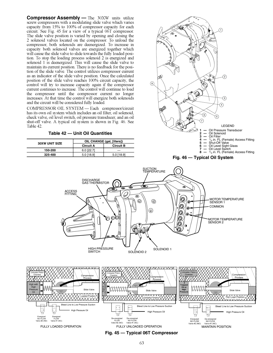
Compressor Assembly — The 30XW units utilize screw compressors with a modulating slide valve which varies capacity from 15% to 100% of compressor capacity for each circuit. See Fig. 45 for a view of a typical 06T compressor. The slide valve position is varied by opening and closing the 2 solenoid valves located on the compressor. To unload the compressor, both solenoids are deenergized. To increase in capacity both solenoid valves are energized together which will cause the slide valve to slide towards the fully loaded posi- tion. To stop the loading process solenoid 2 is energized and solenoid 1 is deenergized. This will cause the slide valve to maintain its current position. There is no feedback for the posi- tion of the slide valve. The control utilizes compressor current as an indicator of the slide valve position. Once the calculated position of the slide valve reaches 100% circuit capacity, the control will try to increase capacity again if the compressor current continues to increase. The control will continue to load the compressor until the compressor current no longer increases. At that time the control will energize both solenoids and the circuit will be considered fully loaded.

COMPRESSOR OIL SYSTEM — Each compressor/circuit has its own oil system which includes an oil filter, oil solenoid, check valve, oil level switch, oil pressure transducer, and an oil shut-off valve. A typical oil system is shown in Fig. 46. See Table 42.

8

6

7

1

2

3

4

5

LEGEND

Table 42 — Unit Oil Quantities

30XW UNIT SIZE

OIL CHANGE (gal, [liters])

Circuit A

Circuit B


150-200

6.0 [22.7]

325-400

5.0 [18.9]

5.0 [18.9]

DISCHARGE

GAS THERMISTOR

ACCESS

FITTING


1

Oil Pressure Transducer


2

Oil Solenoid


3

Oil Filter


4

1/4 in. FL (Female) Access Fitting

A30-4842

5

Shut-Off Valve

6

Oil Level Sight Glass


7

Oil Level Switch


8

1/4 in. FL (Female) Access Fitting

Fig. 46 — Typical Oil System

SUCTION

TEMPERATURE

MOTOR TEMPERATURE

SENSOR 1

COMMON

MOTOR TEMPERATURE

SENSOR 2

HIGH PRESSURE

SOLENOID 1

SWITCH

SOLENOID 2

Unloader Piston


Chamber


Compression


Process

High with


High


Pressure

Discharge

Slide Valve

Oil

Port


Loaded Position


Unloader Piston


Chamber


Compression


Process

Drain to

Low Pressure

Discharge

Port

x

Slide Valve


Unloaded Position

Unloader Piston

Chamber

Trapped

Oil at

High

Pressure

Compression

Process

Slide Valve

Discharge

Port

Part Load Position

Bleed Line to Low Pressure Suction

High Pressure Oil

Energized

Energized

NO FLOW

FLOW

Valve #2 (NO)

Valve #1 (NC)

Bleed Line to Low Pressure Suction

High Pressure Oil

De-energized

De-energized

FLOW

NO FLOW

Valve #2 (NO)

Valve #1 (NC)


Bleed Line to Low Pressure Suction


High Pressure Oil


Energized

De-energized

NO FLOW

NO FLOW

Valve #2 (NO)

Valve #1 (NC)

FULLY LOADED OPERATION

FULLY UNLOADED OPERATION

MAINTAIN POSITION


A30-4841

Fig. 45 — Typical 06T Compressor

63

Page 63
Image 63
Carrier 30XW150-400 specifications Unit Oil Quantities, Discharge GAS Thermistor Access Fitting, Switch Solenoid

30XW150-400 specifications

The Carrier 30XW150-400 series is a line of water-cooled chillers that exemplifies innovation, efficiency, and reliability in commercial cooling solutions. Designed for medium to large-scale applications, this series is ideal for a variety of settings, including commercial buildings, industrial processes, and chilled water systems.

One of the standout features of the Carrier 30XW series is its efficiency. The chillers utilize advanced variable-speed compressor technology, which allows the units to adapt to varying cooling loads while minimizing energy consumption. This technology not only reduces operational costs but also contributes to better environmental sustainability by lowering greenhouse gas emissions.

The 30XW series chillers are equipped with high-efficiency, scroll compressors that operate quietly and provide significant energy savings. By utilizing enhanced economizer controls, these units can achieve higher efficiency ratings, especially in part-load conditions. The result is an impressive Energy Efficiency Ratio (EER) and Seasonal Energy Efficiency Ratio (SEER), making these units a smart choice for energy-conscious businesses.

In terms of reliability, the Carrier 30XW150-400 series features robust construction and an array of safety and monitoring systems. The units come with advanced diagnostics that help in quickly identifying and addressing any operational issues. This proactive approach ensures reliability and minimizes downtime, which is crucial for maintaining optimal temperature controls in critical environments.

Additionally, the chillers incorporate environmentally friendly refrigerants that comply with the latest regulations, making them a sustainable choice for modern commercial applications. Their compact design allows for flexible installation options, and the integrated control systems provide the ability to optimize performance based on specific building management demands.

User-friendly interfaces and remote monitoring capabilities further enhance the ease of operation, allowing facility managers to have real-time insight into performance metrics and system health. This level of control contributes to better maintenance planning and maximizes the lifespan of the equipment.

In summary, the Carrier 30XW150-400 series of water-cooled chillers combines advanced technology, energy efficiency, and reliable performance, making it an ideal solution for various commercial and industrial cooling needs. With its commitment to innovation and sustainability, Carrier continues to set the standard in the HVAC industry.