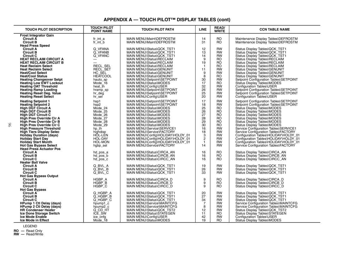
APPENDIX A — TOUCH PILOT™ DISPLAY TABLES (cont)

96

TOUCH PILOT DESCRIPTION

TOUCH PILOT

TOUCH PILOT PATH

LINE

READ/

CCN TABLE NAME

POINT NAME

WRITE


Frost Integrator Gain


Circuit A

fr_int_a

MAIN MENU\Maint\DEFROSTM

14

RO

Maintenance Display Tables\DEFROSTM

Circuit B

fr_int_b

MAIN MENU\Maint\DEFROSTM

31

RO

Maintenance Display Tables\DEFROSTM

Head Press Speed


Circuit A

Q_VFANA

MAIN MENU\Status\QCK_TST1

12

RW

Status Display Tables\QCK_TST1

Circuit B

Q_VFANB

MAIN MENU\Status\QCK_TST1

13

RW

Status Display Tables\QCK_TST1

Circuit C

Q_VFANC

MAIN MENU\Status\QCK_TST1

14

RW

Status Display Tables\QCK_TST1

HEAT RECLAIM CIRCUIT A

MAIN MENU\Status\RECLAIM

9

RO

Status Display Tables\RECLAIM

HEAT RECLAIM CIRCUIT B

MAIN MENU\Status\RECLAIM

19

RO

Status Display Tables\RECLAIM

Heat Reclaim Select

RECL_SEL

MAIN MENU\Status\RECLAIM

1

RO

Status Display Tables\RECLAIM

Heat Reclaim Select

RECL_SET

MAIN MENU\Status\GENUNIT

11

RW

Status Display Tables\GENUNIT

Heat/Cool Select

HC_SEL

MAIN MENU\Status\GENUNIT

9

RW

Status Display Tables\GENUNIT

Heat/Cool Status

HEATCOOL

MAIN MENU\Status\GENUNIT

8

RO

Status Display Tables\GENUNIT

Heating Changeover Setpt

hauto_sp

MAIN MENU\Setpoint\SETPOINT

30

RW

Setpoint Configuration Tables\SETPOINT

Heating Low EWT Lockout

Mode_16

MAIN MENU\Status\MODES

17

RO

Status Display Tables\MODES

Heating OAT Threshold

heat_th

MAIN MENU\Config\USER

32

RW

Configuration Tables\USER

Heating Ramp Loading

hramp_sp

MAIN MENU\Setpoint\SETPOINT

26

RW

Setpoint Configuration Tables\SETPOINT

Heating Reset Deg. Value

hr_deg

MAIN MENU\Setpoint\SETPOINT

25

RW

Setpoint Configuration Tables\SETPOINT

Heating Reset Select

hr_sel

MAIN MENU\Config\USER

20

RW

Configuration Tables\USER

Heating Setpoint 1

hsp1

MAIN MENU\Setpoint\SETPOINT

17

RW

Setpoint Configuration Tables\SETPOINT

Heating Setpoint 2

hsp2

MAIN MENU\Setpoint\SETPOINT

18

RW

Setpoint Configuration Tables\SETPOINT

High DGT Circuit A

Mode_24

MAIN MENU\Status\MODES

25

RO

Status Display Tables\MODES

High DGT Circuit B

Mode_25

MAIN MENU\Status\MODES

26

RO

Status Display Tables\MODES

High DGT Circuit C

Mode_26

MAIN MENU\Status\MODES

27

RO

Status Display Tables\MODES

High Pres Override Cir A

Mode_27

MAIN MENU\Status\MODES

28

RO

Status Display Tables\MODES

High Pres Override Cir B

Mode_28

MAIN MENU\Status\MODES

29

RO

Status Display Tables\MODES

High Pres Override Cir C

Mode_29

MAIN MENU\Status\MODES

30

RO

Status Display Tables\MODES

High Pressure Threshold

hp_th

MAIN MENU\Service\SERVICE1

16

RW

Service Configuration Tables\SERVICE1

High Tiers Display Selec

highdisp

MAIN MENU\Service\FACTORY

18

RW

Service Configuration Tables\FACTORY

Holiday Duration (days)

HOL-LEN

MAIN MENU\Config\HOLIDAY\HOLDY_01

3

RW

Configuration Tables\HOLIDAY\HOLDY_01

Holiday Start Day

HOL-DAY

MAIN MENU\Config\HOLIDAY\HOLDY_01

2

RW

Configuration Tables\HOLIDAY\HOLDY_01

Holiday Start Month

HOL-MON

MAIN MENU\Config\HOLIDAY\HOLDY_01

1

RW

Configuration Tables\HOLIDAY\HOLDY_01

Hot Gas Bypass Select

hgbp_sel

MAIN MENU\Service\FACTORY

14

RW

Service Configuration Tables\FACTORY

Head Press Actuator Pos


Circuit A

hd_pos_a

MAIN MENU\Status\CIRCA_AN

16

RO

Status Display Tables\CIRCA_AN

Circuit B

hd_pos_b

MAIN MENU\Status\CIRCB_AN

16

RO

Status Display Tables\CIRCB_AN

Circuit C

hd_pos_c

MAIN MENU\Status\CIRCC_AN

16

RO

Status Display Tables\CIRCC_AN

Heater Ball Valve


Circuit A

Q_BVL_A

MAIN MENU\Status\QCK_TST1

19

RW

Status Display Tables\QCK_TST1

Circuit B

Q_BVL_B

MAIN MENU\Status\QCK_TST1

26

RW

Status Display Tables\QCK_TST1

Circuit C

Q_BVL_C

MAIN MENU\Status\QCK_TST1

33

RW

Status Display Tables\QCK_TST1

Hot Gas Bypass Output


Circuit A

HGBP_A

MAIN MENU\Status\CIRCA_D

9

RO

Status Display Tables\CIRCA_D

Circuit B

HGBP_B

MAIN MENU\Status\CIRCB_D

9

RO

Status Display Tables\CIRCB_D

Circuit C

HGBP_C

MAIN MENU\Status\CIRCC_D

9

RO

Status Display Tables\CIRCC_D

Hot Gas Bypass


Circuit A

Q_HGBP_A

MAIN MENU\Status\QCK_TST1

20

RW

Status Display Tables\QCK_TST1

Circuit B

Q_HGBP_B

MAIN MENU\Status\QCK_TST1

27

RW

Status Display Tables\QCK_TST1

Circuit C

Q_HGBP_C

MAIN MENU\Status\QCK_TST1

34

RW

Status Display Tables\QCK_TST1

HPump 1 Ctl Delay (days)

hpump1_c

MAIN MENU\Service\MAINTCFG

7

RW

Service Configuration Tables\MAINTCFG

HPump 2 Ctl Delay (days)

hpump2_c

MAIN MENU\Service\MAINTCFG

8

RW

Service Configuration Tables\MAINTCFG

HR Condenser Heater

Q_CD_HT

MAIN MENU\Status\QCK_TST2

12

RW

Status Display Tables\QCK_TST2

Ice Done Storage Switch

ICE_SW

MAIN MENU\Status\STATEGEN

11

RO

Status Display Tables\STATEGEN

Ice Mode Enable

ice_cnfg

MAIN MENU\Config\USER

42

RW

Configuration Tables\USER

Ice Mode in Effect

Mode_18

MAIN MENU\Status\MODES

19

RO

Status Display Tables\MODES

LEGEND

RO — Read Only

RW — Read/Write

Page 96
Image 96
Carrier 30XW150-400 specifications Heat Reclaim Circuit a, Heat Reclaim Circuit B

30XW150-400 specifications

The Carrier 30XW150-400 series is a line of water-cooled chillers that exemplifies innovation, efficiency, and reliability in commercial cooling solutions. Designed for medium to large-scale applications, this series is ideal for a variety of settings, including commercial buildings, industrial processes, and chilled water systems.

One of the standout features of the Carrier 30XW series is its efficiency. The chillers utilize advanced variable-speed compressor technology, which allows the units to adapt to varying cooling loads while minimizing energy consumption. This technology not only reduces operational costs but also contributes to better environmental sustainability by lowering greenhouse gas emissions.

The 30XW series chillers are equipped with high-efficiency, scroll compressors that operate quietly and provide significant energy savings. By utilizing enhanced economizer controls, these units can achieve higher efficiency ratings, especially in part-load conditions. The result is an impressive Energy Efficiency Ratio (EER) and Seasonal Energy Efficiency Ratio (SEER), making these units a smart choice for energy-conscious businesses.

In terms of reliability, the Carrier 30XW150-400 series features robust construction and an array of safety and monitoring systems. The units come with advanced diagnostics that help in quickly identifying and addressing any operational issues. This proactive approach ensures reliability and minimizes downtime, which is crucial for maintaining optimal temperature controls in critical environments.

Additionally, the chillers incorporate environmentally friendly refrigerants that comply with the latest regulations, making them a sustainable choice for modern commercial applications. Their compact design allows for flexible installation options, and the integrated control systems provide the ability to optimize performance based on specific building management demands.

User-friendly interfaces and remote monitoring capabilities further enhance the ease of operation, allowing facility managers to have real-time insight into performance metrics and system health. This level of control contributes to better maintenance planning and maximizes the lifespan of the equipment.

In summary, the Carrier 30XW150-400 series of water-cooled chillers combines advanced technology, energy efficiency, and reliable performance, making it an ideal solution for various commercial and industrial cooling needs. With its commitment to innovation and sustainability, Carrier continues to set the standard in the HVAC industry.