Carrier 30XW150-400 specifications Appendix A - Touch Pilot Display Tables

Models: 30XW150-400

1 148
Download 148 pages 52.93 Kb
Page 86
Image 86

86

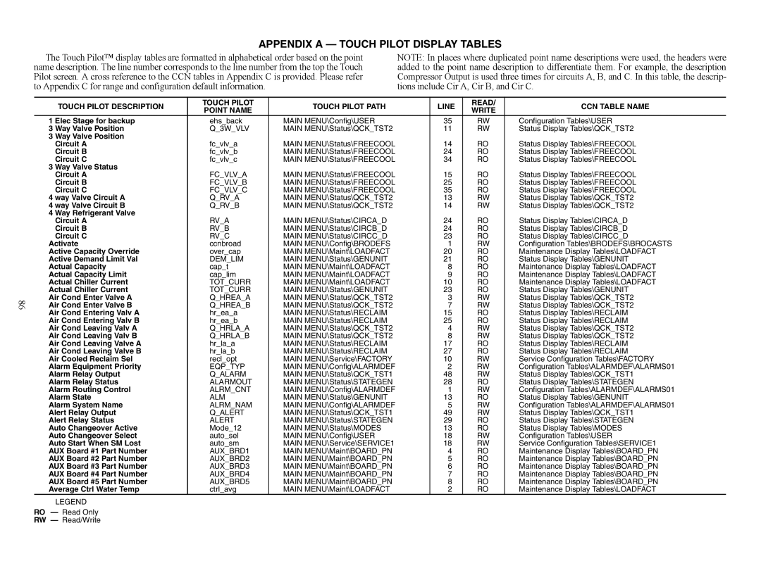
APPENDIX A — TOUCH PILOT DISPLAY TABLES

The Touch Pilot™ display tables are formatted in alphabetical order based on the point

NOTE: In places where duplicated point name descriptions were used, the headers were

name description. The line number corresponds to the line number from the top the Touch

added to the point name description to differentiate them. For example, the description

Pilot screen. A cross reference to the CCN tables in Appendix C is provided. Please refer

Compressor Output is used three times for circuits A, B, and C. In this table, the descrip-

to Appendix C for range and configuration default information.


tions include Cir A, Cir B, and Cir C.


TOUCH PILOT DESCRIPTION

TOUCH PILOT

TOUCH PILOT PATH


LINE

READ/

CCN TABLE NAME

POINT NAME


WRITE


1 Elec Stage for backup

ehs_back

MAIN MENU\Config\USER


35

RW

Configuration Tables\USER

3 Way Valve Position

Q_3W_VLV

MAIN MENU\Status\QCK_TST2


11

RW

Status Display Tables\QCK_TST2

3 Way Valve Position


Circuit A

fc_vlv_a

MAIN MENU\Status\FREECOOL


14

RO

Status Display Tables\FREECOOL

Circuit B

fc_vlv_b

MAIN MENU\Status\FREECOOL


24

RO

Status Display Tables\FREECOOL

Circuit C

fc_vlv_c

MAIN MENU\Status\FREECOOL


34

RO

Status Display Tables\FREECOOL

3 Way Valve Status


Circuit A

FC_VLV_A

MAIN MENU\Status\FREECOOL


15

RO

Status Display Tables\FREECOOL

Circuit B

FC_VLV_B

MAIN MENU\Status\FREECOOL


25

RO

Status Display Tables\FREECOOL

Circuit C

FC_VLV_C

MAIN MENU\Status\FREECOOL


35

RO

Status Display Tables\FREECOOL

4 way Valve Circuit A

Q_RV_A

MAIN MENU\Status\QCK_TST2


13

RW

Status Display Tables\QCK_TST2

4 way Valve Circuit B

Q_RV_B

MAIN MENU\Status\QCK_TST2


14

RW

Status Display Tables\QCK_TST2

4 Way Refrigerant Valve


Circuit A

RV_A

MAIN MENU\Status\CIRCA_D


24

RO

Status Display Tables\CIRCA_D

Circuit B

RV_B

MAIN MENU\Status\CIRCB_D


24

RO

Status Display Tables\CIRCB_D

Circuit C

RV_C

MAIN MENU\Status\CIRCC_D


23

RO

Status Display Tables\CIRCC_D

Activate

ccnbroad

MAIN MENU\Config\BRODEFS


1

RW

Configuration Tables\BRODEFS\BROCASTS

Active Capacity Override

over_cap

MAIN MENU\Maint\LOADFACT


20

RO

Maintenance Display Tables\LOADFACT

Active Demand Limit Val

DEM_LIM

MAIN MENU\Status\GENUNIT


21

RO

Status Display Tables\GENUNIT

Actual Capacity

cap_t

MAIN MENU\Maint\LOADFACT


8

RO

Maintenance Display Tables\LOADFACT

Actual Capacity Limit

cap_lim

MAIN MENU\Maint\LOADFACT


9

RO

Maintenance Display Tables\LOADFACT

Actual Chiller Current

TOT_CURR

MAIN MENU\Maint\LOADFACT


10

RO

Maintenance Display Tables\LOADFACT

Actual Chiller Current

TOT_CURR

MAIN MENU\Status\GENUNIT


23

RO

Status Display Tables\GENUNIT

Air Cond Enter Valve A

Q_HREA_A

MAIN MENU\Status\QCK_TST2


3

RW

Status Display Tables\QCK_TST2

Air Cond Enter Valve B

Q_HREA_B

MAIN MENU\Status\QCK_TST2


7

RW

Status Display Tables\QCK_TST2

Air Cond Entering Valv A

hr_ea_a

MAIN MENU\Status\RECLAIM


15

RO

Status Display Tables\RECLAIM

Air Cond Entering Valv B

hr_ea_b

MAIN MENU\Status\RECLAIM


25

RO

Status Display Tables\RECLAIM

Air Cond Leaving Valv A

Q_HRLA_A

MAIN MENU\Status\QCK_TST2


4

RW

Status Display Tables\QCK_TST2

Air Cond Leaving Valv B

Q_HRLA_B

MAIN MENU\Status\QCK_TST2


8

RW

Status Display Tables\QCK_TST2

Air Cond Leaving Valve A

hr_la_a

MAIN MENU\Status\RECLAIM


17

RO

Status Display Tables\RECLAIM

Air Cond Leaving Valve B

hr_la_b

MAIN MENU\Status\RECLAIM


27

RO

Status Display Tables\RECLAIM

Air Cooled Reclaim Sel

recl_opt

MAIN MENU\Service\FACTORY


10

RW

Service Configuration Tables\FACTORY

Alarm Equipment Priority

EQP_TYP

MAIN MENU\Config\ALARMDEF


2

RW

Configuration Tables\ALARMDEF\ALARMS01

Alarm Relay Output

Q_ALARM

MAIN MENU\Status\QCK_TST1


48

RW

Status Display Tables\QCK_TST1

Alarm Relay Status

ALARMOUT

MAIN MENU\Status\STATEGEN


28

RO

Status Display Tables\STATEGEN

Alarm Routing Control

ALRM_CNT

MAIN MENU\Config\ALARMDEF


1

RW

Configuration Tables\ALARMDEF\ALARMS01

Alarm State

ALM

MAIN MENU\Status\GENUNIT


13

RO

Status Display Tables\GENUNIT

Alarm System Name

ALRM_NAM

MAIN MENU\Config\ALARMDEF


5

RW

Configuration Tables\ALARMDEF\ALARMS01

Alert Relay Output

Q_ALERT

MAIN MENU\Status\QCK_TST1


49

RW

Status Display Tables\QCK_TST1

Alert Relay Status

ALERT

MAIN MENU\Status\STATEGEN


29

RO

Status Display Tables\STATEGEN

Auto Changeover Active

Mode_12

MAIN MENU\Status\MODES


13

RO

Status Display Tables\MODES

Auto Changeover Select

auto_sel

MAIN MENU\Config\USER


18

RW

Configuration Tables\USER

Auto Start When SM Lost

auto_sm

MAIN MENU\Service\SERVICE1


18

RW

Service Configuration Tables\SERVICE1

AUX Board #1 Part Number

AUX_BRD1

MAIN MENU\Maint\BOARD_PN


4

RO

Maintenance Display Tables\BOARD_PN

AUX Board #2 Part Number

AUX_BRD2

MAIN MENU\Maint\BOARD_PN


5

RO

Maintenance Display Tables\BOARD_PN

AUX Board #3 Part Number

AUX_BRD3

MAIN MENU\Maint\BOARD_PN


6

RO

Maintenance Display Tables\BOARD_PN

AUX Board #4 Part Number

AUX_BRD4

MAIN MENU\Maint\BOARD_PN


7

RO

Maintenance Display Tables\BOARD_PN

AUX Board #5 Part Number

AUX_BRD5

MAIN MENU\Maint\BOARD_PN


8

RO

Maintenance Display Tables\BOARD_PN

Average Ctrl Water Temp

ctrl_avg

MAIN MENU\Maint\LOADFACT


2

RO

Maintenance Display Tables\LOADFACT

LEGEND

RO — Read Only

RW — Read/Write

Page 86
Image 86
Carrier 30XW150-400 specifications Appendix A - Touch Pilot Display Tables