6


5


F)

4


(deg


Cooling Reset


Deg. Value,


Reset


3

DGRC


Current No Reset Value,


Degrees


CRV1


2


Current Full Reset Value,


1


CRV2


0


0

2

4

6

8

10

12

14

16

18

20


mA Signal


a30-4482


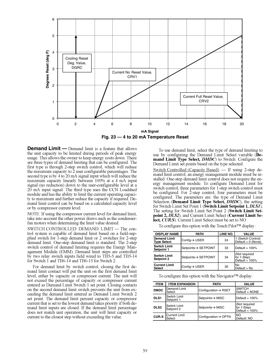
Fig. 23 — 4 to 20 mA Temperature Reset

Demand Limit — Demand limit is a feature that allows the unit capacity to be limited during periods of peak energy usage. This allows the owner to keep energy costs down. There are three types of demand limiting that can be configured. The first type is through 2-step switch control, which will reduce the maximum capacity to 2 user configurable percentages. The second type is by 4 to 20 mA signal input which will reduce the maximum capacity linearly between 100% at a 4 mA input signal (no reduction) down to the user-configurable level at a 20 mA input signal. The third type uses the CCN Loadshed module and has the ability to limit the current operating capaci- ty to maximum and further reduce the capacity if required. De- mand limit control can be based on a calculated capacity level or by compressor current level.

NOTE: If using the compressor current level for demand limit, take into account the other power draws such as the condenser- fan motors when determining the limit value desired.

SWITCH CONTROLLED DEMAND LIMIT — The con- trol system is capable of demand limit based on a field-sup- plied switch for 1-step demand limit or 2 switches for 2-step demand limit. One-step demand limit is standard. The 2-step switch control of demand limiting requires the Energy Man- agement Module (EMM). Demand limit steps are controlled by two relay switch inputs field wired to TB5-5 and TB5-14 for Switch 1 and TB6-14 and TB6-15 for Switch 2.

For demand limit by switch control, closing the first de- mand limit contact will put the unit on the first demand limit level, either by capacity or compressor current. The unit will not exceed the percentage of capacity or compressor current entered as Demand Limit Switch 1 set point. Closing contacts on the second demand limit switch prevents the unit from ex- ceeding the demand limit entered as Demand Limit Switch 2 set point. The demand limit percent capacity or compressor current that is set to the lowest demand takes priority if both de- mand limit inputs are closed. If the demand limit percentage does not match unit operation, the unit will limit capacity or current to the closest step without exceeding the value.

To use demand limit, select the type of demand limiting to use by configuring the Demand Limit Select variable (De- mand Limit Type Select, DMDC) to Switch. Configure the Demand Limit set points based on the type selected.

Switch Controlled (Capacity Based) — If using 2-step de- mand limit control, an energy management module must be in- stalled. One-step demand limit control does not require the en- ergy management module. To configure Demand Limit for switch control, three parameters for 1-step switch control must be configured. For 2-step control, four parameters must be configured. The parameters are: the type of Demand Limit Selection (Demand Limit Type Select, DMDC), the setting for Switch Limit Set Point 1 (Switch Limit Setpoint 1, DLS1), The setting for Switch Limit Set Point 2 (Switch Limit Set- point 2, DLS2), and Current Limit Select (Current Limit Se- lect, CUR.S). Current Limit Select must be set to NO.

To configure this option with the Touch Pilot™ display:

DISPLAY NAME

PATH

LINE NO.

VALUE

Demand Limit

ConfigUSER

24

1 (Switch Control)

Type Select

Default = 0 (None)


Switch Limit

SetpointsSETPOINT

33

Default = 100%

Setpoint 1


Switch Limit

SetpointsSETPOINT


(Not required

34

for 1-Step)

Setpoint 2


Default = 100%


Current Limit

ConfigUSER

30

No

Select

Default = No


To configure this option with the Navigator™ display:

ITEM

ITEM EXPANSION

PATH

VALUE

DMDC

Demand Limit

ConfigurationRSET

SWITCH


Select


Default = NONE

DLS1

Switch Limit

SetpointsMISC

Default = 100%

Setpoint 1


DLS2

Switch Limit

SetpointsMISC

(Not required

for 1-Step)

Setpoint 2


Default = 100%


CUR.S

Current Limit

ConfigurationOPTN

NO


Select


Default: NO

39

Page 39
Image 39
Carrier 30XW150-400 specifications Reset, Item Expansion Path Value Dmdc, DLS1, DLS2, Cur.S

30XW150-400 specifications

The Carrier 30XW150-400 series is a line of water-cooled chillers that exemplifies innovation, efficiency, and reliability in commercial cooling solutions. Designed for medium to large-scale applications, this series is ideal for a variety of settings, including commercial buildings, industrial processes, and chilled water systems.

One of the standout features of the Carrier 30XW series is its efficiency. The chillers utilize advanced variable-speed compressor technology, which allows the units to adapt to varying cooling loads while minimizing energy consumption. This technology not only reduces operational costs but also contributes to better environmental sustainability by lowering greenhouse gas emissions.

The 30XW series chillers are equipped with high-efficiency, scroll compressors that operate quietly and provide significant energy savings. By utilizing enhanced economizer controls, these units can achieve higher efficiency ratings, especially in part-load conditions. The result is an impressive Energy Efficiency Ratio (EER) and Seasonal Energy Efficiency Ratio (SEER), making these units a smart choice for energy-conscious businesses.

In terms of reliability, the Carrier 30XW150-400 series features robust construction and an array of safety and monitoring systems. The units come with advanced diagnostics that help in quickly identifying and addressing any operational issues. This proactive approach ensures reliability and minimizes downtime, which is crucial for maintaining optimal temperature controls in critical environments.

Additionally, the chillers incorporate environmentally friendly refrigerants that comply with the latest regulations, making them a sustainable choice for modern commercial applications. Their compact design allows for flexible installation options, and the integrated control systems provide the ability to optimize performance based on specific building management demands.

User-friendly interfaces and remote monitoring capabilities further enhance the ease of operation, allowing facility managers to have real-time insight into performance metrics and system health. This level of control contributes to better maintenance planning and maximizes the lifespan of the equipment.

In summary, the Carrier 30XW150-400 series of water-cooled chillers combines advanced technology, energy efficiency, and reliable performance, making it an ideal solution for various commercial and industrial cooling needs. With its commitment to innovation and sustainability, Carrier continues to set the standard in the HVAC industry.