Chapter 4 Replacing Cisco 7201
Removing and Installing an AC Power Supply
Caution To ensure adequate airflow across the router power supplies, a power supply must be installed in each power supply bay.
You are finished removing the AC power supply. To install the AC power supply, go to the “Installing the AC Power Supply” section on page
Installing the AC Power Supply
This section provides information about installing an AC power supply in the Cisco 7201 router.
Warning Never install an AC power module and a DC power module in the same chassis. Statement 1050
Warning Installation of the equipment must comply with local and national electrical codes. Statement 1074
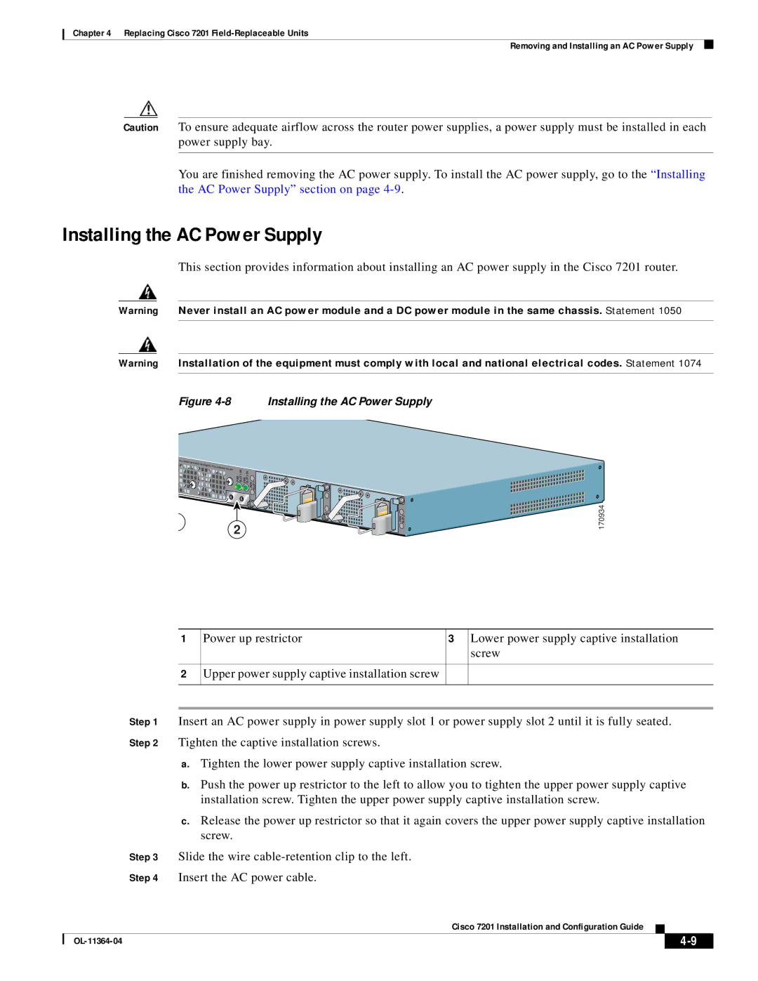
Figure 4-8 Installing the AC Power Supply
PWR SLOT 1 OK PWR SLOT 2 OK PWR SLOT 1 |
|
PWR SLOT 2 | 170934 |
2 |
|
1
2
Power up restrictor | 3 | Lower power supply captive installation |
|
| screw |
Upper power supply captive installation screw |
|
|
|
|
|
Step 1 Insert an AC power supply in power supply slot 1 or power supply slot 2 until it is fully seated. Step 2 Tighten the captive installation screws.
a.Tighten the lower power supply captive installation screw.
b.Push the power up restrictor to the left to allow you to tighten the upper power supply captive installation screw. Tighten the upper power supply captive installation screw.
c.Release the power up restrictor so that it again covers the upper power supply captive installation screw.
Step 3 Slide the wire
Step 4 Insert the AC power cable.
Cisco 7201 Installation and Configuration Guide
|
| ||
|
|