Chapter 2 Installing the Cisco 7201 Router
Installing the Router
To install the
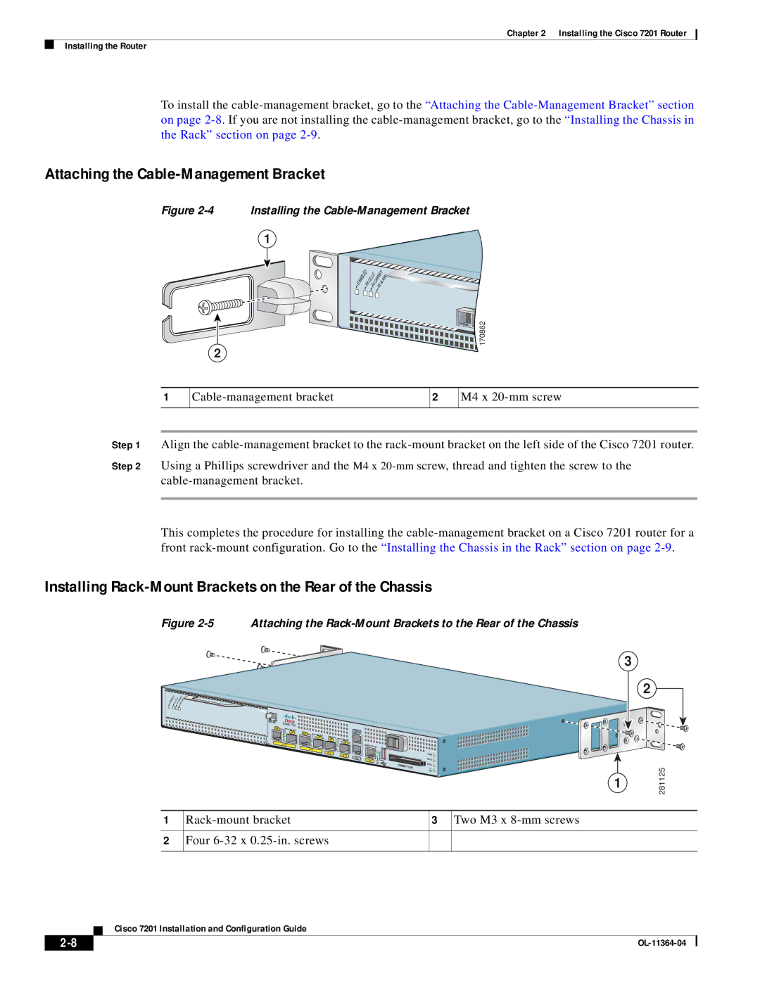
Attaching the Cable-Management Bracket
Figure
2
Installing the
1
ENABLED |
|
|
| ALARM |
| RX | CELLS | CARRIER | |
| RX | RX |
| |
![]()
![]()
![]()
![]()
![]()
![]() 170862
170862
1
2
M4 x
Step 1 Align the
Step 2 Using a Phillips screwdriver and the M4 x
This completes the procedure for installing the
Installing Rack-Mount Brackets on the Rear of the Chassis
Figure 2-5 Attaching the Rack-Mount Brackets to the Rear of the Chassis
ENABLED |
|
| CARR | ALARM |
|
| CELLS | IER | |
| RX |
|
| |
| RX | RX |
| |
ATM 
RJ45 |
| Cisco 7201 |
|
|
|
|
|
|
|
|
EN | LINK/ACTV |
|
|
|
|
| CONSOLE |
|
| |
|
| SFP | RJ45 EN | LINK/ACTV |
|
|
|
|
| |
|
|
| LINK/ACTV |
|
|
|
|
| ||
|
|
| TX | SFP RX |
| LINK/ACTV |
|
| ||
PA |
|
|
|
| SFP | TX |
|
| ||
|
|
|
|
| SFP | RX |
|
| ||
S |
| GE 0/0 |
|
|
|
|
|
| ||
LOT 1 |
|
|
|
|
|
| MNGMNT USE ONLY |
| ||
|
|
| GE 0/1 |
|
|
|
|
| ||
|
|
|
|
|
|
|
|
|
| |
|
|
|
|
| GE 0/2 |
| GE 0/3 |
|
|
|
|
|
|
|
|
|
| AUX |
|
| |
|
|
|
|
|
|
|
|
|
| |
|
|
|
|
|
|
|
| FE 0/0 | FE | 0 |
|
|
|
|
|
|
|
|
| LINK | COMPACT FLASH |
|
|
|
|
|
|
|
|
|
| |
ALARM ![]() PWR OK
PWR OK ![]()
![]()
![]() STATUS
STATUS ![]()
CF ACTV
3
2
1 | 281125 |
|
1
2
3 Two M3 x |
Four
Cisco 7201 Installation and Configuration Guide
| ||
|