Chapter 2 Installing the Cisco 7201 Router
Using the
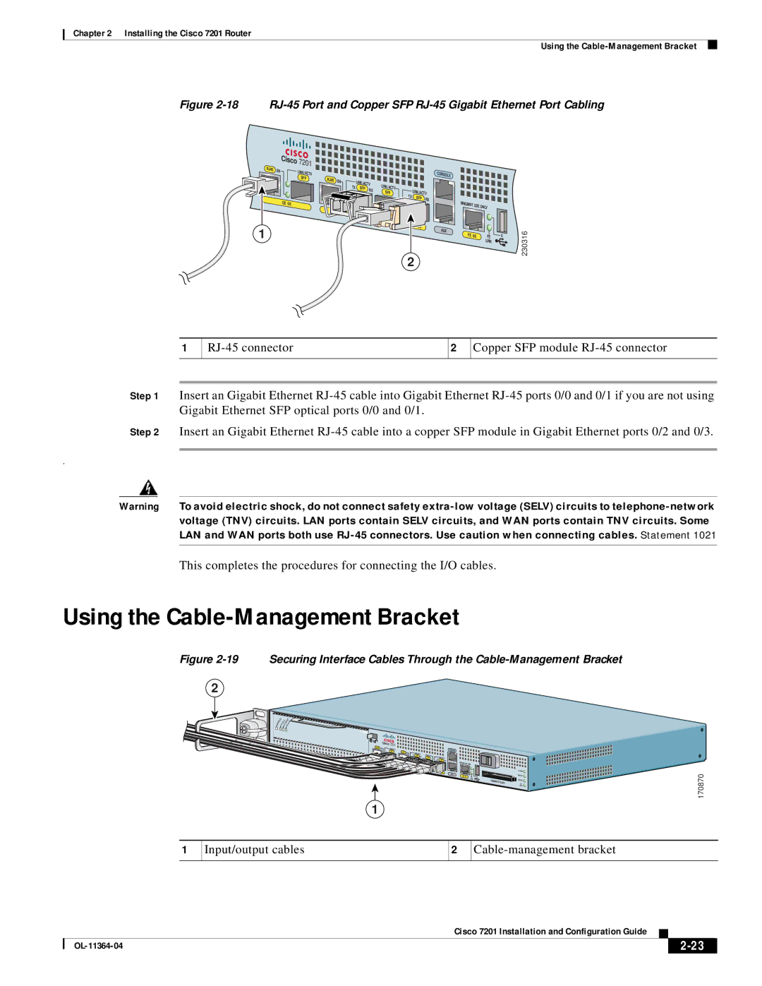
Figure 2-18 RJ-45 Port and Copper SFP RJ-45 Gigabit Ethernet Port Cabling
1
|
| Cisco | 7201 |
|
|
|
|
|
|
|
|
|
RJ45 |
|
|
|
|
|
|
|
|
|
|
| |
EN |
| LINK/ACTV |
|
|
|
|
|
| CONSOLE |
|
| |
|
|
|
|
|
|
|
|
|
| |||
|
|
|
|
|
|
|
|
|
|
| ||
|
|
| SFP | RJ45 |
|
|
|
|
|
|
| |
|
|
| EN | LINK/ACTV |
|
|
|
|
| |||
|
|
|
|
|
|
|
|
| ||||
|
|
|
|
| TX | LINK/ACTV |
|
|
|
| ||
|
|
|
|
| SFP | RX |
| LINK/ACTV |
|
| ||
|
|
|
|
|
|
| SFP |
|
|
| ||
|
|
|
|
|
|
|
| TX |
|
| ||
|
|
|
|
|
|
|
|
| RX |
|
| |
|
| GE 0/0 |
|
|
|
|
|
|
|
|
| |
|
|
|
|
|
|
|
|
| MNGMNT USE |
| ||
|
|
|
|
|
|
|
|
|
|
| ONLY |
|
|
|
|
|
|
|
|
|
|
| 0/3 |
|
|
|
|
|
|
|
|
|
|
|
| AUX |
|
|
|
|
|
|
|
|
|
|
|
| FE 0/0 | FE | 0 |
|
|
|
|
|
|
|
|
|
|
| LINK |
|
2
230316
1
2
Copper SFP module
Step 1 Insert an Gigabit Ethernet
Step 2 Insert an Gigabit Ethernet
.
Warning To avoid electric shock, do not connect safety
This completes the procedures for connecting the I/O cables.
Using the Cable-Management Bracket
Figure
2
Securing Interface Cables Through the
ENABLED XC | XC | R |
| |
ALA | M | |||
| LLS | RIE |
| |
E | AR | R | ||
R | R | RX |
|
|
ATM |
|
|
|
|
|
|
|
|
|
|
RJ45 |
| Cisco 7201 |
|
|
|
|
|
|
|
|
EN | LINK/ACTV |
|
|
|
|
|
|
| CONSOLE | |
|
| RJ45 |
|
|
|
|
|
| ||
|
| SFP | EN | LINK/ACTV |
|
|
|
| ||
|
|
|
| TX | SFP | RX | LINK/ACTV |
| LINK/ACTV | |
PA |
|
|
|
|
|
| SFP | TX | ||
SLOT 1 |
| GE 0/0 |
|
|
|
|
|
| SFP | RX |
|
|
|
|
|
|
|
| MNGMNT USE ONLY | ||
|
|
|
| GE 0/1 |
|
|
|
|
| |
|
|
|
|
|
|
|
|
|
| |
|
|
|
|
|
|
| GE 0/2 |
| GE 0/3 | ALARM |
AUX | FE | 0 | PWR | OK |
FE 0/0 |
| |||
| LINK | COMPACT | STATUS | |
|
| FLASH | CF | |
|
|
| ACTV | |
170870
1
1 | Input/output cables | 2 |
|
|
|
|
|
|
| Cisco 7201 Installation and Configuration Guide |
|
| |
|
|
| |||
|
|
|
| ||
|
|
|
| ||