Chapter 2 Installing the Cisco 7201 Router
Installing the Router
For
For
Two-Post Rack Installation
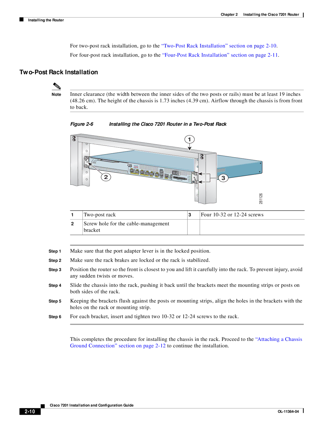
Note Inner clearance (the width between the inner sides of the two posts or rails) must be at least 19 inches (48.26 cm). The height of the chassis is 1.73 inches (4.39 cm). Airflow through the chassis is from front to back.
Figure 2-6 Installing the Cisco 7201 Router in a Two-Post Rack
1
A | D | CELLS | CARRIER | |
BLE | ||||
EN |
| RX ALARM | ||
RX | RX |
ATM ![]()
RJ45
PA
SLOT 1
2
Cisco
EN
GE 0/0
7201 |
|
|
|
|
|
|
|
|
|
|
|
LINK/ACTV | RJ45 |
|
|
|
|
| CONSOLE |
|
|
|
|
SFP | EN | LINK/ACTV |
|
|
|
|
|
|
| ||
|
| TX | SFP | RX | LINK/ACTV | LINK/ACTV |
|
|
|
| |
|
|
|
| SFP |
|
|
|
| |||
|
|
|
|
| TX | SFP | RX |
|
|
|
|
|
| GE 0/1 |
|
|
|
| MNGMNT USE ONLY |
|
|
| |
|
|
|
|
|
|
|
|
|
| 3 | |
|
|
|
|
| GE 0/2 | GE 0/3 |
|
|
| ALARM | |
|
|
|
|
|
| AUX |
|
| |||
|
|
|
|
|
|
|
|
| PWR OK | ||
|
|
|
|
|
|
| FE 0/0 | FE | 0 | ||
|
|
|
|
|
|
|
| LINK | COMPACT | STATUS | |
|
|
|
|
|
|
|
|
| FLASH | CF | |
|
|
|
|
|
|
|
|
|
| ACTV | |
|
|
| 281126 |
|
|
|
|
1 | 3 | Four | |
|
|
|
|
2 | Screw hole for the |
|
|
| bracket |
|
|
|
|
|
|
Step 1 Make sure that the port adapter lever is in the locked position.
Step 2 Make sure the rack brakes are locked or the rack is stabilized.
Step 3 Position the router so the front is closest to you and lift it carefully into the rack. To prevent injury, avoid any sudden twists or moves.
Step 4 Slide the chassis into the rack, pushing it back until the brackets meet the mounting strips or posts on both sides of the rack.
Step 5 Keeping the brackets flush against the posts or mounting strips, align the holes in the brackets with the holes on the rack or mounting strip.
Step 6 For each bracket, insert and tighten two
This completes the procedure for installing the chassis in the rack. Proceed to the “Attaching a Chassis Ground Connection” section on page
| Cisco 7201 Installation and Configuration Guide |