Chapter 4 Replacing Cisco 7201
Removing and Installing an AC Power Supply
Caution To ensure the proper flow of cooling air across the internal components, make sure a port adapter blank panel is installed in the unoccupied port adapter slot.
This completes the port adapter installation procedure. For information about configuring a port adapter, see the Cisco 7201 Port Adapter Documentation Roadmap which provides a linked list of all port adapter documentation for the Cisco 7201 router.
Removing and Installing an AC Power Supply
For AC power supply specifications and product numbers, see Appendix A, “Specifications.”
This section provides information about removing and replacing an AC power supply. Because of the power supply redundancy, there is no need to power off the Cisco 7201 router before removing one of the AC power supplies.
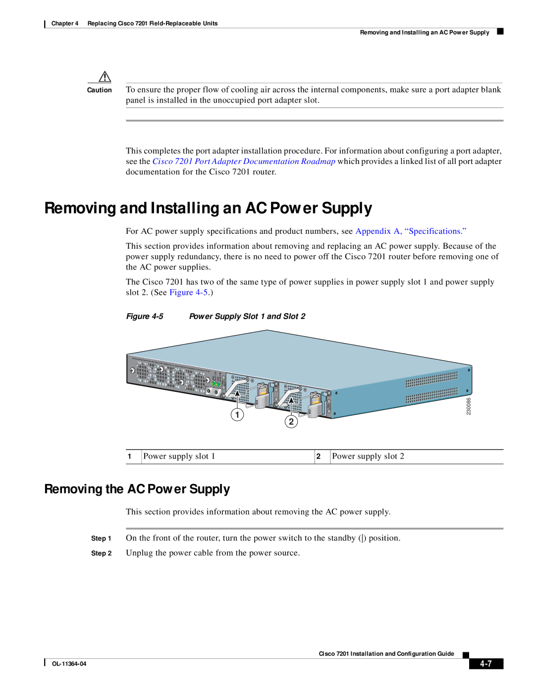
The Cisco 7201 has two of the same type of power supplies in power supply slot 1 and power supply slot 2. (See Figure
Figure 4-5 Power Supply Slot 1 and Slot 2
SLOT 1
PWR
SLOT 2 OK
PWR
SLOT 1 OK
PWR
1
PWR SLOT 2 | 230086 |
2
1
Power supply slot 1
2
Power supply slot 2
Removing the AC Power Supply
This section provides information about removing the AC power supply.
Step 1 On the front of the router, turn the power switch to the standby () position.
Step 2 Unplug the power cable from the power source.
Cisco 7201 Installation and Configuration Guide
|
| ||
|
|