Chapter 2 Installing the Cisco 7201 Router
Connecting Power
Step 8 Attach the other end of the ground wires to an appropriate grounding point at your site.
Step 9 Repeat Step 1 through Step 8 on the second DC power supply.
Wiring the DC-Input Power Source
Note The color coding of the
Warning When installing or replacing the unit, the ground connection must always be made first and disconnected last. Statement 1046
Warning StatThis product relies on the building’s installation for
Statement 1005
Warning Before performing any of the following procedures, ensure that power is removed from the DC circuit. Statement 1003
Warning Only trained and qualified personnel should be allowed to install, replace, or service this equipment. Statement 1030
Use the information in this section to wire the
Step 1 At the front of the router, make sure the power switch is in the standby () position.
Step 2 Move the
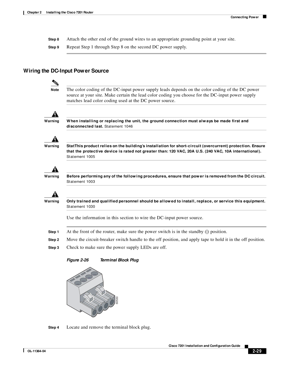
Figure 2-26 Terminal Block Plug

![]() 60530
60530
Step 4 Locate and remove the terminal block plug.
|
| Cisco 7201 Installation and Configuration Guide |
|
| |
|
|
| |||
|
|
|
| ||
|
|
|
| ||