Appendix A Specifications
SFP Module Specifications and Configurations
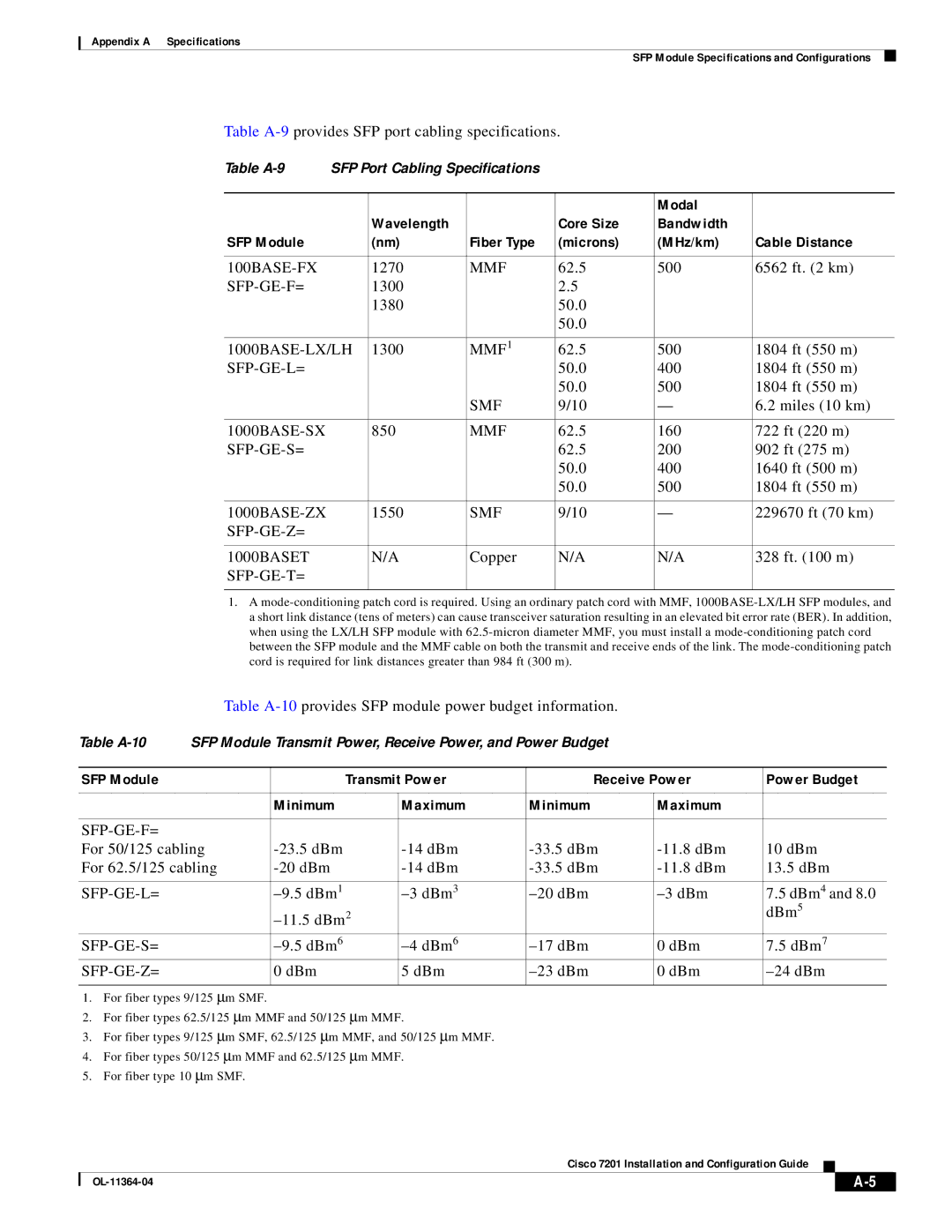
Table
Table | SFP Port Cabling Specifications |
|
|
| ||
|
|
|
|
|
|
|
|
|
|
|
| Modal |
|
|
| Wavelength |
| Core Size | Bandwidth |
|
SFP Module |
| (nm) | Fiber Type | (microns) | (MHz/km) | Cable Distance |
|
|
|
|
|
|
|
|
| 1270 | MMF | 62.5 | 500 | 6562 ft. (2 km) |
| 1300 |
| 2.5 |
|
| |
|
| 1380 |
| 50.0 |
|
|
|
|
|
| 50.0 |
|
|
|
|
|
|
|
| |
| 1300 | MMF1 | 62.5 | 500 | 1804 ft (550 m) | |
|
|
| 50.0 | 400 | 1804 ft (550 m) | |
|
|
|
| 50.0 | 500 | 1804 ft (550 m) |
|
|
| SMF | 9/10 | — | 6.2 miles (10 km) |
|
|
|
|
|
|
|
| 850 | MMF | 62.5 | 160 | 722 ft (220 m) | |
|
|
| 62.5 | 200 | 902 ft (275 m) | |
|
|
|
| 50.0 | 400 | 1640 ft (500 m) |
|
|
|
| 50.0 | 500 | 1804 ft (550 m) |
|
|
|
|
|
|
|
| 1550 | SMF | 9/10 | — | 229670 ft (70 km) | |
|
|
|
|
|
|
|
|
|
|
|
|
|
|
1000BASET |
| N/A | Copper | N/A | N/A | 328 ft. (100 m) |
|
|
|
|
|
| |
|
|
|
|
|
|
|
1.A
Table
Table | SFP Module Transmit Power, Receive Power, and Power Budget |
|
| ||||
|
|
|
|
|
|
|
|
SFP Module |
|
| Transmit Power | Receive Power | Power Budget | ||
|
|
|
|
|
|
|
|
|
| Minimum |
| Maximum | Minimum | Maximum |
|
|
|
|
|
|
|
|
|
|
|
|
|
|
|
| |
For 50/125 cabling |
| 10 dBm | |||||
For 62.5/125 cabling |
| 13.5 dBm | |||||
|
|
|
|
|
|
|
|
|
| 7.5 dBm4 and 8.0 | |||||
|
|
|
|
| dBm5 | ||
|
| 0 dBm | 7.5 dBm7 | ||||
|
| 0 dBm |
| 5 dBm |
| 0 dBm |
|
|
|
|
|
|
|
|
|
1.For fiber types 9/125 ∝m SMF.
2.For fiber types 62.5/125 ∝m MMF and 50/125 ∝m MMF.
3.For fiber types 9/125 ∝m SMF, 62.5/125 ∝m MMF, and 50/125 ∝m MMF.
4.For fiber types 50/125 ∝m MMF and 62.5/125 ∝m MMF.
5.For fiber type 10 ∝m SMF.
Cisco 7201 Installation and Configuration Guide
| ||
|