Chapter 1 Overview
Cisco 7201 Hardware Overview
CompactFlash Disk Information
The Cisco 7201 router has one CompactFlash Disk slot that uses CompactFlash Disks. The device in this slot is always addressed as disk0: when using Cisco IOS
CompactFlash Disks are smaller in size than Type 2 Flash Disks but provide the same AT Attachment (ATA) interface and equivalent functionality. This interface complies with the ANSI ATA Interface Document X3T13.1153 D Rev. 9 specification. CompactFlash Disks provide from 256 MB of storage.
The CompactFlash Disk has controller circuitry that allows it to emulate a hard disk and automatically maps out bad blocks and performs automatic block erasure. The CompactFlash Disk also provides the capability to allocate noncontiguous sectors, which eliminates the need for the squeeze command (which was required with
The CompactFlash Disk also supports the Cisco IOS File System feature, which provides a single interface to all of the router’s file systems, including the Flash Disks and flash memory, as well as network file systems such as File Transfer Protocol (FTP) and Trivial FTP (TFTP) servers.
Table
Rear View
This section provides information about the power supplies and fans on the rear of the Cisco 7201 router.
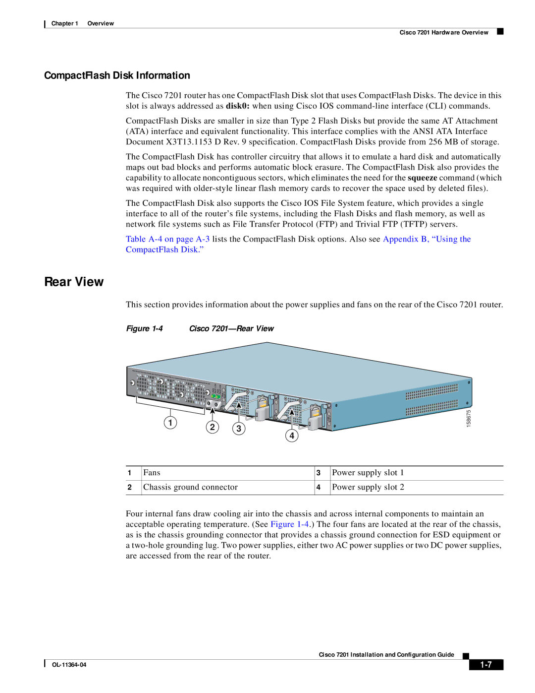
Figure 1-4 Cisco 7201—Rear View
|
| PWR SLOT 1 OK | PWR SLOT 2 OK PWR SLOT 1 |
|
|
|
| 1 | 2 | 3 |
| PWR SLOT 2 | 158675 |
|
| 4 |
|
| ||
|
|
|
|
|
| |
1 | Fans |
|
| 3 | Power supply slot 1 | |
2 | Chassis ground connector | 4 |
| Power supply slot 2 | ||
Four internal fans draw cooling air into the chassis and across internal components to maintain an acceptable operating temperature. (See Figure
Cisco 7201 Installation and Configuration Guide
|
| ||
|
|