Chapter 5 Troubleshooting Initial Startup Problems
Problem Solving Using a Subsystems Approach
•The PWR OK (power ok) LED is green when the system has powered on and is attempting to boot the software, or has booted the software.
•The ENABLED LED on the port adapter or service adapter comes on when the processor completes its initialization of the adapter for operation. An ENABLED LED indicates that the adapter is receiving power and has been recognized by the processor; it does not indicate the state of the individual interfaces on the adapters. If an ENABLED LED fails to come on, proceed to the “Upgrading the Boot Helper (Boot Loader) Image” section on page
•When all LEDs come on to indicate that the system has booted successfully, the initial system banner should be displayed on the console screen. If it is not displayed, see Appendix A, “Specifications” to verify that the terminal is set correctly and that it is properly connected to the console port. If the ALARM LED is on, check the STATUS LED and PWR OK LED.
Troubleshooting the Power Subsystem
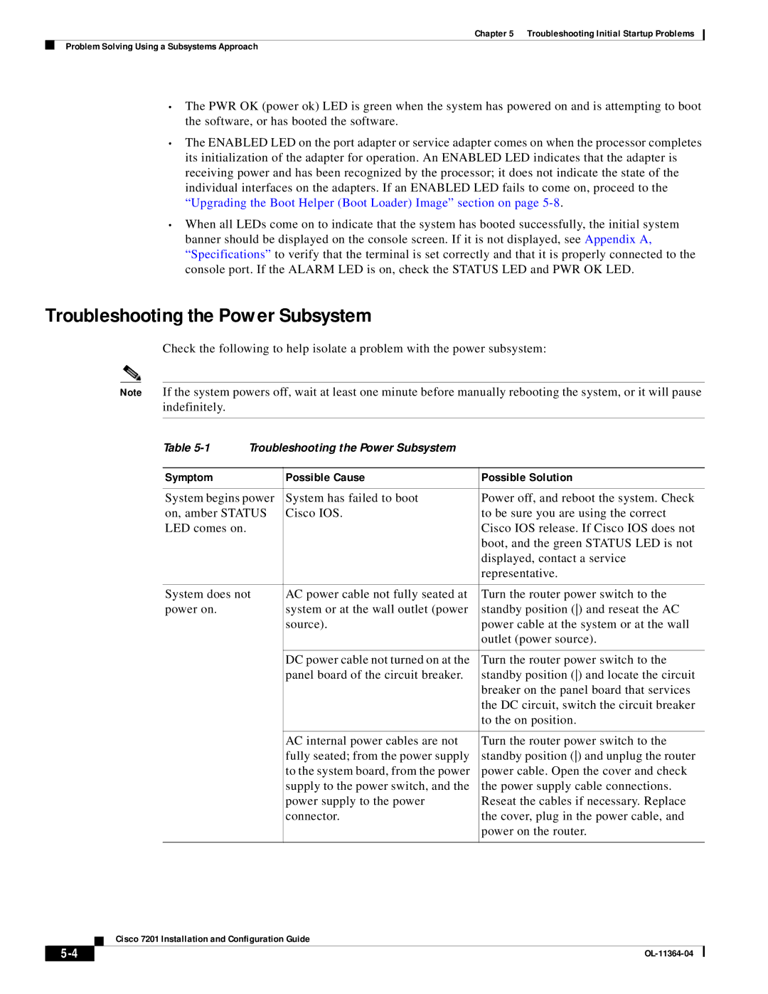
Check the following to help isolate a problem with the power subsystem:
Note If the system powers off, wait at least one minute before manually rebooting the system, or it will pause indefinitely.
Table | Troubleshooting the Power Subsystem |
| |
|
|
|
|
Symptom |
| Possible Cause | Possible Solution |
|
|
| |
System begins power | System has failed to boot | Power off, and reboot the system. Check | |
on, amber STATUS | Cisco IOS. | to be sure you are using the correct | |
LED comes on. |
|
| Cisco IOS release. If Cisco IOS does not |
|
|
| boot, and the green STATUS LED is not |
|
|
| displayed, contact a service |
|
|
| representative. |
|
|
| |
System does not | AC power cable not fully seated at | Turn the router power switch to the | |
power on. |
| system or at the wall outlet (power | standby position () and reseat the AC |
|
| source). | power cable at the system or at the wall |
|
|
| outlet (power source). |
|
|
|
|
|
| DC power cable not turned on at the | Turn the router power switch to the |
|
| panel board of the circuit breaker. | standby position () and locate the circuit |
|
|
| breaker on the panel board that services |
|
|
| the DC circuit, switch the circuit breaker |
|
|
| to the on position. |
|
|
|
|
|
| AC internal power cables are not | Turn the router power switch to the |
|
| fully seated; from the power supply | standby position () and unplug the router |
|
| to the system board, from the power | power cable. Open the cover and check |
|
| supply to the power switch, and the | the power supply cable connections. |
|
| power supply to the power | Reseat the cables if necessary. Replace |
|
| connector. | the cover, plug in the power cable, and |
|
|
| power on the router. |
|
|
|
|
Cisco 7201 Installation and Configuration Guide
| ||
|
