Chapter 2 Installing the Cisco 7201 Router
Connecting I/O Cables
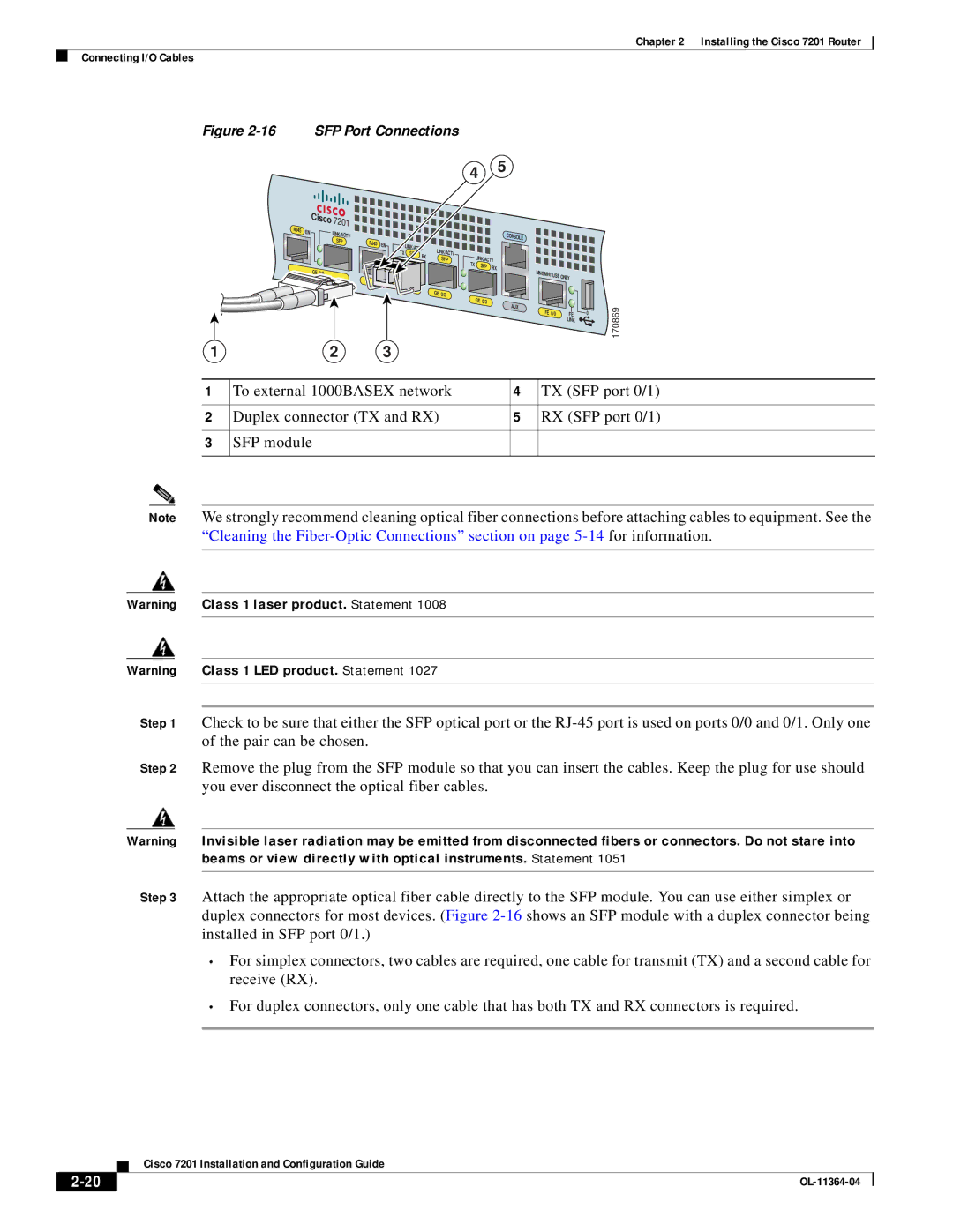
Figure 2-16 SFP Port Connections
4 5
|
| Cisco | 7201 |
|
|
|
|
|
|
|
|
|
|
RJ45 |
|
|
|
|
|
|
|
|
|
|
|
| |
EN |
| LINK/ACTV |
|
|
|
|
|
|
| CONSOLE |
|
| |
|
|
|
|
|
|
|
|
|
|
| |||
|
|
|
|
|
|
|
|
|
|
|
| ||
|
|
| SFP | RJ45 |
|
|
|
|
|
|
|
| |
|
|
| EN | LINK/ACTV |
|
|
|
|
|
| |||
|
|
|
|
|
|
|
|
|
| ||||
|
|
|
|
| TX | LINK/ACTV |
|
|
|
|
| ||
|
|
|
|
| SFP | RX |
| LINK/ACTV |
|
| |||
|
|
|
|
|
|
| SFP |
|
|
| |||
|
|
|
|
|
|
|
| TX |
|
| |||
|
|
|
|
|
|
|
|
| SFP | RX |
|
| |
|
| GE 0/0 |
|
|
|
|
|
|
|
|
| ||
|
|
|
|
|
|
|
|
|
| MNGMNT USE |
| ||
|
|
|
|
|
|
|
|
|
|
|
| ONLY |
|
|
|
|
|
|
|
|
| GE 0/2 |
| GE 0/3 |
|
|
|
|
|
|
|
|
|
|
|
|
| AUX |
|
| |
|
|
|
|
|
|
|
|
|
|
|
|
| |
|
|
|
|
|
|
|
|
|
|
| FE 0/0 | FE | 0 |
|
|
|
|
|
|
|
|
|
|
|
| LINK |
|
170869
1 | 2 | 3 |
|
|
|
|
|
| |
1 | To external 1000BASEX network | 4 | TX (SFP port 0/1) | |
|
|
|
| |
2 | Duplex connector (TX and RX) | 5 | RX (SFP port 0/1) | |
|
|
|
|
|
3 | SFP module |
|
|
|
|
|
|
|
|
Note We strongly recommend cleaning optical fiber connections before attaching cables to equipment. See the “Cleaning the
Warning Class 1 laser product. Statement 1008
Warning Class 1 LED product. Statement 1027
Step 1 Check to be sure that either the SFP optical port or the
Step 2 Remove the plug from the SFP module so that you can insert the cables. Keep the plug for use should you ever disconnect the optical fiber cables.
Warning Invisible laser radiation may be emitted from disconnected fibers or connectors. Do not stare into beams or view directly with optical instruments. Statement 1051
Step 3 Attach the appropriate optical fiber cable directly to the SFP module. You can use either simplex or duplex connectors for most devices. (Figure
•For simplex connectors, two cables are required, one cable for transmit (TX) and a second cable for receive (RX).
•For duplex connectors, only one cable that has both TX and RX connectors is required.
| Cisco 7201 Installation and Configuration Guide |