Chapter 2 Installing the Cisco 7201 Router
Connecting Power
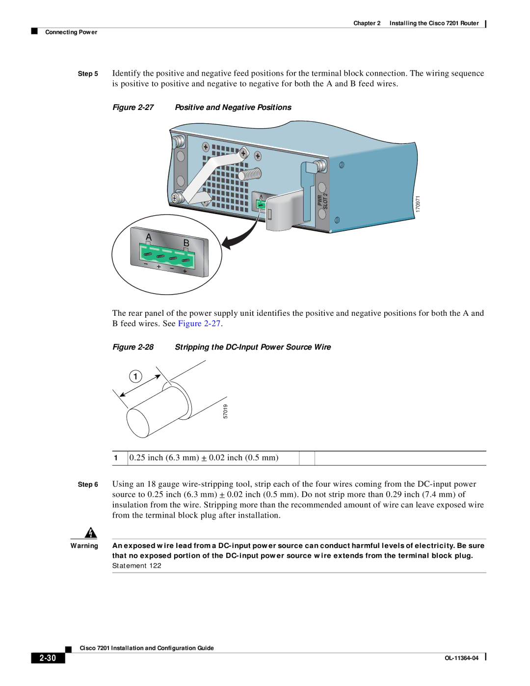
Step 5 Identify the positive and negative feed positions for the terminal block connection. The wiring sequence is positive to positive and negative to negative for both the A and B feed wires.
Figure 2-27 Positive and Negative Positions
A | B |
|
A | B |
|
PWR SLOT 2 | 170971 |
The rear panel of the power supply unit identifies the positive and negative positions for both the A and B feed wires. See Figure
Figure 2-28 Stripping the DC-Input Power Source Wire
1
57019
1
0.25 inch (6.3 mm) + 0.02 inch (0.5 mm)
Step 6 Using an 18 gauge
Warning An exposed wire lead from a
| Cisco 7201 Installation and Configuration Guide |