Manuals
/
Dell
/
Computer Equipment
/
Server
Dell
R510
owner manual
107, Fan cable Installing System Components
Models:
R510
1
107
216
216
Download
216 pages
48.79 Kb
104
105
106
107
108
109
110
111
Troubleshooting
Install
Error codes
Password
Fault. Power
E2017 Timer refresh
Hard-Drive Indicator Patterns
CPU config
Will now reset
Diagnostic Lights Optional
Page 107
Image 107
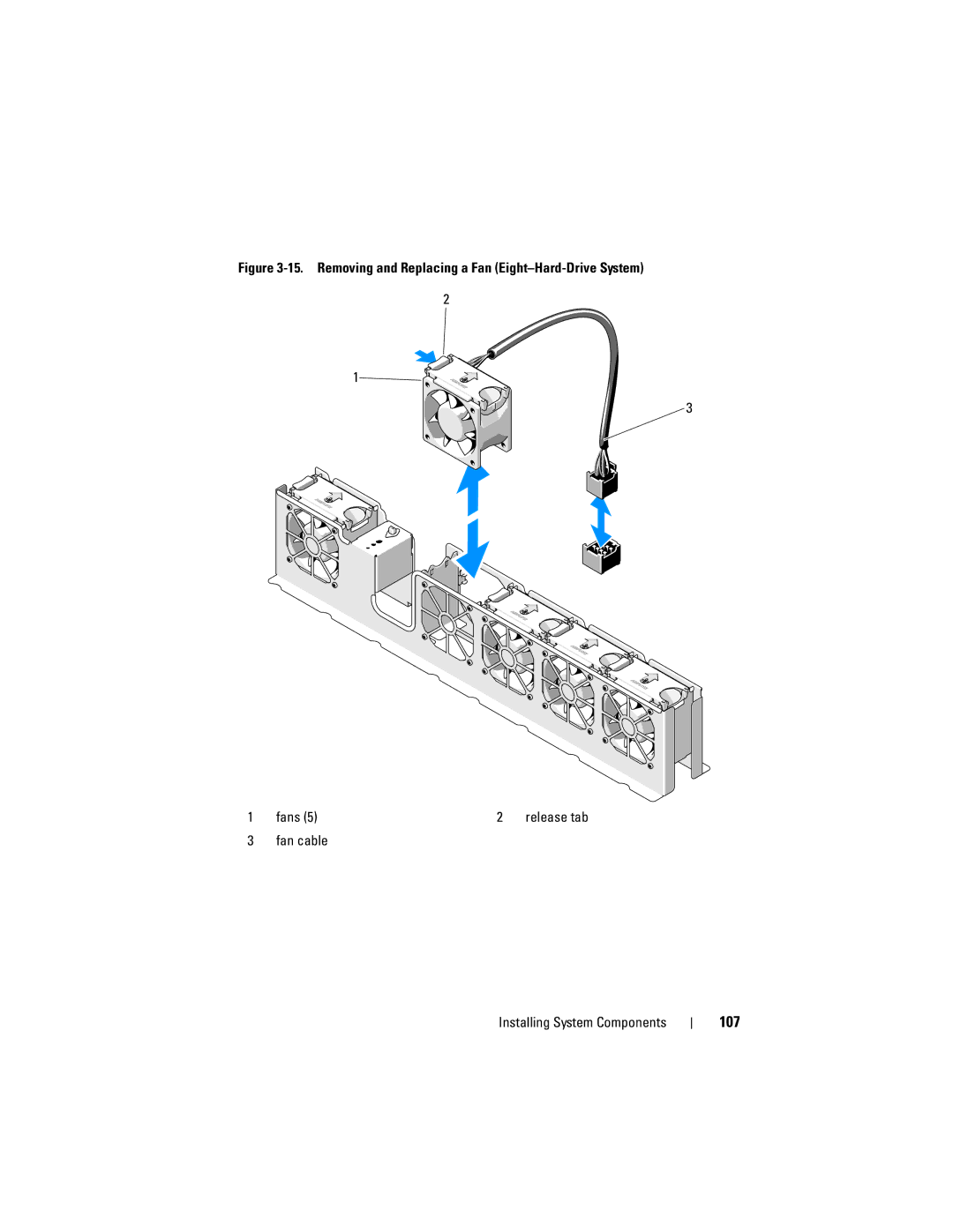
Figure
3-15.
Removing and Replacing a Fan
(Eight–Hard-Drive
System)
2
1
3
1
fans (5)
2
release tab
3
fan cable
Installing System Components
107
Page 106
Page 108
Page 107
Image 107
Page 106
Page 108
Contents
Dell PowerEdge R510 Systems
November
Contents
Other Information You May Need
Processor Settings Screen Sata Settings Screen Optional
Entering the Uefi Boot Manager
Uefi Boot Settings Screen
Removing the Cooling Shroud Installing the Cooling Shroud
Entering the BMC Setup Module
Entering the iDRAC Configuration Utility
Installing a Redundant Power Supply
Installing a Hard Drive Into a
Installing an Optical Drive
Removing a Redundant Power Supply
122
General Memory Module Installation
114
115
161
Replacing the System Battery 143
143
146
176
165
191
Disabling a Forgotten Password 196 Contents
189
190
Getting Help Contacting Dell Glossary Index
Contents
Accessing System Features During Startup
Front-Panel Features and Indicators
Has been powered on
System error messages
LCD panel displays an error
AC power and an error has been
Lights Optional on
Optical drive
Optional Drive or DVD+/-RW drive
NMI button Used to troubleshoot software
Five seconds
LCD Panel Features Buttons Description Left
LCD Panel Features Optional
Buttons Description Select
Home Screen
View Menu
Setup Menu
Green Green and amber About Your System
Hard-Drive Indicator Patterns
Option Description Power
Display format can be configured in the Set home
Back-Panel Features and Indicators About Your System
Back-Panel Features and Indicators
Embedded 10/100/1000 NIC
PCIe expansion card Connectors
Slots using riser card
Optional
Supply
Power supply 2 PS2
Power supply 1 PS1
NIC Indicator Codes
Guidelines for Connecting Optional External Devices
Power Indicator Codes
Diagnostic Lights Optional
Resource and/or system Board hardware failure
Installed in your system
System. If the problem persists
Information on the drives
LCD Status Messages Optional
Check Battery E1211 RAID
Disabled
Power
Battery
E122D Memory
E122C CPU Power
Fault. Power
E122A
E1410 System Fatal
CPU config
Bios revision
Error. Power
### W error
Check Error
E1610 Power Supply #
Check power Supply E1614 Power Supply #
Config
E1620 Power Supply #
Power error
E1624 Lost power
E1711 PCI parity
Error on #
E1714 Unknown error
Fault. Review
E1A14 SAS cable a
Configuration
Configured but
Unusable Check DIMMs E2013 Bios unable to
Power cycle
Failure. Power
E2017 Timer refresh
Timer error
E201D Shutdown test
E201A SuperIO
E201B Keyboard
Initialization
E2021 Incorrect
During Post Check screen Message E2023 Bios Unable to
E2110 Multibit Error
Disabled on
I1910 Intrusion
##. Power
I1920 iDRAC6 Upgrade
E2113 Mem mirror OFF
Degraded
Solving Problems Described by LCD Status Messages
Removing LCD Status Messages
W1628 Performance
System Messages
Alert! Node
Rebooting
Alert! iDRAC6 not
Responding
Memory disabled
Alert! Power
System boot
Power down
CPU x installed
Bios Update
Is installed on
System board Please run Setup
Sizes detected
Bootable media
CPUs with
Different cache
Embedded NICx
Configuration on
Each CPU should
Match
May not work
Accessible USB
Keyboard fuse has
Local keyboard
Memory tests
Mirror mode
Installed Pairs. Pairs must Be matched in size and geometry
Memory set to
Available
No boot device
No timer tick
Error Expected
Detected after
Read fault Requested sector not found
Plug & Play
Quad rank Dimm
Shutdown failure
Seek error
Sector not found
Seek operation
Thermal sensor
Setup program
DIMMs should
Following DIMMs should
Counter 2 failed
Timer chip
Will now reset
System Services
Mode x,x,x
Protected mode
Installed
When in mirror
Code update
When in 128-bit
Error has caused
System reset
Frequencies to
Reboot
Configuration is
Degraded. CPU
Selected drive
Write fault
Write fault on
Alert Messages
Diagnostics Messages
Other Information You May Need
Choosing the System Boot Mode
Using the System Setup Program and Uefi Boot Manager
Displays the System Setup programs help file
Entering the System Setup Program
Responding to Error Messages
Using the System Setup Program Navigation Keys
Main Screen
System Setup Options
Settings Screen on
Option Description
See Power Management Screen on
Password on page 78 for more information
On default Key keyboards Report Keyboard
Memory Settings Screen
Processor Settings Screen
Boot Settings Screen
Sata Settings Screen Optional
Integrated Devices Screen
Boot Sequence Retry
Disabled default System reattempts to boot after 30 seconds
NICs. The NICs may also be accessed through
Serial Communication Screen
PCI IRQ Assignments Screen
Embedded Server Management Screen
System Security Screen
Power Management Screen
Pre-boot measurements
Option Description Setup Password
Disabled at system start-up
If On without Pre-boot Measurements, the system
Exit Screen
Enables or disables the NMI feature
Using the Uefi Boot Manager Navigation Keys
Entering the Uefi Boot Manager
System Utilities Screen
Uefi Boot Manager Screen
Uefi Boot Settings Screen
Bootable DOS media with diagnostics software
System and Setup Password Features
Using the System Password
Option Description System Services
Using the System Setup Program and Uefi Boot Manager
Using the Setup Password
Embedded System Management
Baseboard Management Controller Configuration
Try again
IDRAC Configuration Utility
Entering the BMC Setup Module
Entering the iDRAC Configuration Utility
Using the System Setup Program and Uefi Boot Manager
Inside the System
Installing System Components
Recommended Tools
System cooling fans
Power supply bays Cooling shroud Heat sink/processor
Hard drives Installing System Components
Expansion-card riser
SAS backplane Hard drives Installing System Components
Removing the Front Bezel
Front Bezel Optional
Opening the System
Installing the Front Bezel
Opening and Closing the System
Latch release lock
Closing the System
Removing the Cooling Shroud
Cooling Shroud
Removing a Hard-Drive Blank
Installing the Cooling Shroud
Hard Drives
Removing a Hot-Swap Hard Drive
Installing a Hard-Drive Blank
Removing and Installing a Hot-Swap Hard Drive Release button
Installing a Hot-Swap Hard Drive
Close the handle to lock the drive in place
Drive carrier Screws Installing System Components
Removing a Hard Drive From a Hard-Drive Carrier
Removing a Cabled Hard Drive
Installing a Hard Drive Into a Hard-Drive Carrier
Tab Drive bracket
Installing a Cabled Hard Drive
Replace the system cover. See Closing the System on
Installing System Components
Removing a Hard Drive From a Hard-Drive Carrier
Came with the product
Internal Hard Drives
Removing an Internal Hard Drive Bay
100
101
Installing an Internal Hard Drive Bay
Installing a Hard Drive Into a Hard-Drive Bay
103
Optical Drive Optional
Removing an Optical Drive
Release tab
Installing an Optical Drive
105
Came with the product Installing System Components
Cooling Fans
Removing a Cooling Fan
106
107
Fan cable Installing System Components
Fan cable
108
109
Power Supplies
Replacing a Cooling Fan
Removing a Redundant Power Supply
Velcro strap Release latch
Installing a Redundant Power Supply
111
Removing a Non-Redundant Power Supply
Removing the Power Supply Blank
Installing the Power Supply Blank
113
114
Installing a Non-Redundant Power Supply
System Memory
115
General Memory Module Installation Guidelines
GB and 2-GB UDIMMs are supported for a total of up to 16 GB
Mode-Specific Guidelines
Single Processor Dual Processor Memory
117
All 16-GB Mirroring
Sample Udimm Memory Configurations Per Processor
118
119
Installing Memory Modules
Installing System Components
121
Removing Memory Modules
Expansion Cards and Expansion-Card Risers
Expansion Card Installation Guidelines
Scsi controllers
All the slots are x8 connectors
123
Perc 6/E controller
Installing an Expansion Card
Expansion card
Connect any cables to the expansion card
125
Removing an Expansion Card
127
Removing an Expansion-Card Riser
Expansion-card riser Expansion card slot Riser guide posts
Installing an Expansion-Card Riser
Riser guides
129
Integrated Storage Controller Card
Removing the Storage Controller Card
130
SAS data cable connector Release lever blue
131
Installing the Storage Controller Card
IDRAC6 Express Card Optional
Installing an iDRAC6 Express Card
Notch Clip
Removing an iDRAC6 Express Card
133
IDRAC6 Enterprise Card Optional
Installing an iDRAC6 Enterprise Card
Retention standoff posts
135
Removing an iDRAC6 Enterprise Card
Removing a VFlash Media Card
Installing a VFlash Media Card
VFlash Media Optional
Internal USB Memory Key
Removing a Processor
Processors
139
Retention screws
141
Installing a Processor
143
System Battery
Replacing the System Battery
28. Replacing the System Battery System battery
145
146
RAID Battery Optional
Removing the RAID Battery
RAID battery
147
Control Panel Assembly-LED Optional
Installing the RAID Battery
Removing the Control Panel Assembly Four-Hard-Drive System
148
149
Installing the Control Panel Assembly Four-Hard-Drive System
Pull tab
150
151
Control Panel Assembly-LCD Optional
Removing the Control Panel Display Module
Removing the Control Panel Assembly
Installing the Control Panel Display Module
153
USB memory key connector Power cable Control panel board
LCD display module Installing System Components
Removing the Front-Panel IO Module Twelve-Hard-Drive System
Installing the Control Panel Assembly
Front-Panel IO Module Optional
155
Removing the SAS Backplane
SAS Backplane
157
SAS a cable SAS backplane Retention hooks
158
159
USB cable SAS backplane cable Installing System Components
Installing the SAS Backplane
161
Power Distribution Board
Removing the Power Distribution Board
162
163
Unpack the new power distribution board assembly
Replacing the Power Distribution Board
165
System Board
Removing the System Board
166
38. Removing and Installing the System Board Screws
167
Installing the System Board
Unpack the new system board
Installing System Components
169
Troubleshooting External Connections
Troubleshooting Your System
Troubleshooting a USB Device
Troubleshooting the Video Subsystem
171
Troubleshooting a Serial I/O Device
Troubleshooting a NIC
Troubleshooting a Wet System
173
Troubleshooting the System Battery
Troubleshooting a Damaged System
175
Troubleshooting Power Supplies
Troubleshooting a Fan
Troubleshooting System Cooling Problems
177
Troubleshooting System Memory
Troubleshooting Your System
179
Troubleshooting an Internal USB Key
Troubleshooting an Optical Drive
181
Troubleshooting a Hard Drive
Troubleshooting an Internal Hard Drive
183
Troubleshooting a Storage Controller
Troubleshooting Expansion Cards
185
Troubleshooting Processors
187
188
189
Using Online Diagnostics
Embedded System Diagnostics Features
Running the System Diagnostics
Running the Embedded System Diagnostics
When to Use the Embedded System Diagnostics
Selecting Diagnostics Options
Embedded System Diagnostics Testing Options
Using the Custom Test Options
Selecting Devices for Testing
Viewing Information and Results
System Board Jumpers
Default The password feature is enabled pins
System Board Jumper Settings
Password feature is disabled
194
System Board Connectors
195
Password enable jumper
Disabling a Forgotten Password
Expansion-card riser connector
IDRAC6 Express IDRAC6 Express card connector
197
198
Getting Help
Contacting Dell
199
200
Glossary
201
Amperes AC Alternating current
CPU Central processing unit. See processor DC Direct current
202
203
204
Mm Millimeters Ms Milliseconds
205
206
207
TCP/IP Transmission Control Protocol/Internet Protocol
208
System memory See RAM
209
210
Index
211
Using Dell PowerEdge Diagnostics
Diagnostics Advanced testing options, 191 testing options
213
Post
NIC, 171 processors
Unified Server Configurator Lifecyle Controller Upgrades
System Utilities screen, 75 Uefi Boot Settings screen
215
USB
Processor
Top
Page
Image
Contents