6Disconnect the display module cable from the control panel board. See Figure
7Remove the two Phillips screws that secure the control panel board to the system chassis and remove the board.
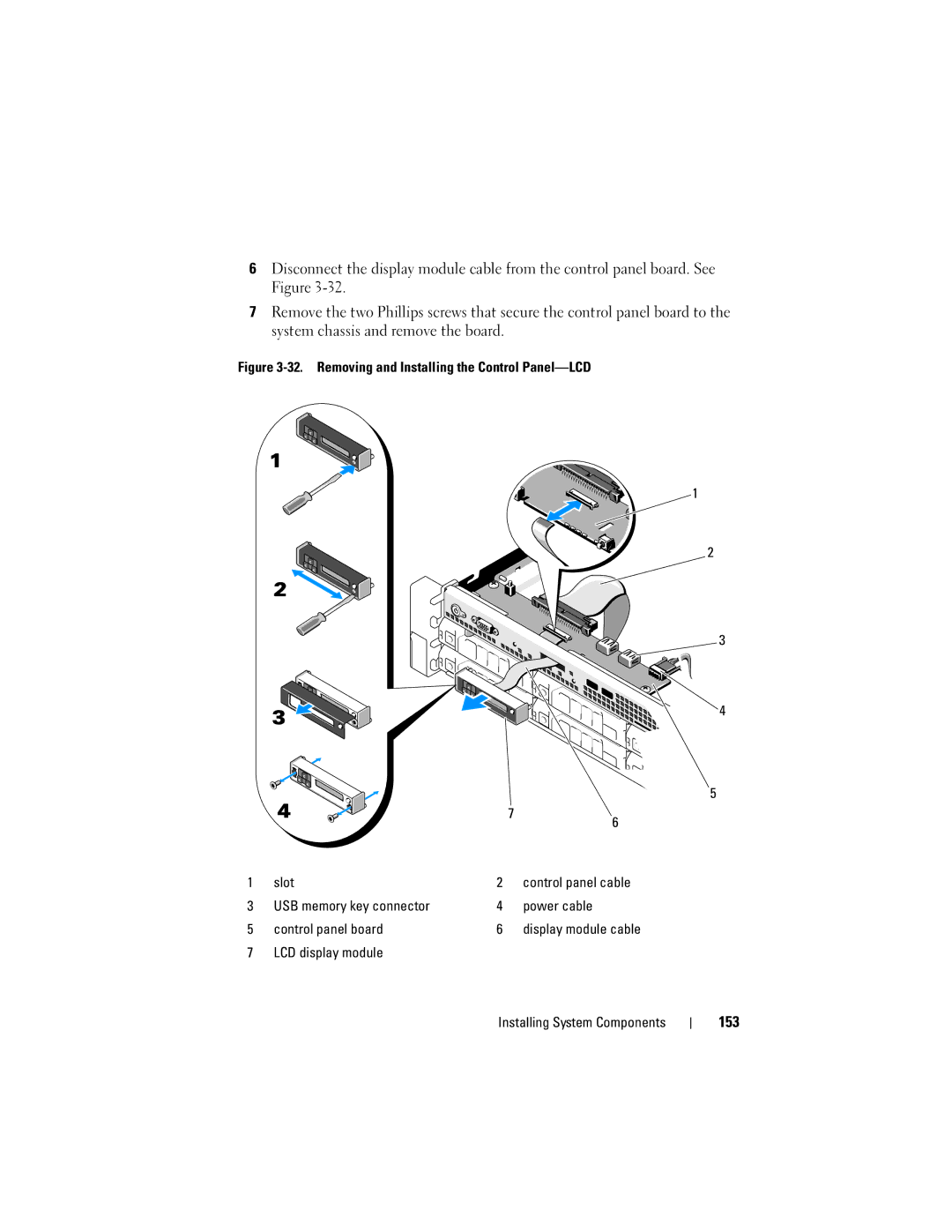
Figure 3-32. Removing and Installing the Control Panel—LCD
1
2
3
4
5
|
|
| 7 | 6 |
|
|
|
| |
1 | slot | 2 |
| control panel cable |
3 | USB memory key connector | 4 |
| power cable |
5 | control panel board | 6 |
| display module cable |
7 | LCD display module |
|
|
|