SRS | Appendix B |
|
|
INSTALLING THE | In some installations, the NT1 and |
| power are located at the user's |
ISDN equipment may be installed | desk. |
in a number of configurations. In |
|
most installations, the | Two drawings are included that |
supplementary equipment (NT1 | illustrate the connections you |
and power) is located in a wire | may need to make when the |
closet in your building. If this is | power and NT1 are located at the |
the case in your installation, | user's desk. |
please skip to the section below: |
|
“Connecting to the Network”. |
|
|
|
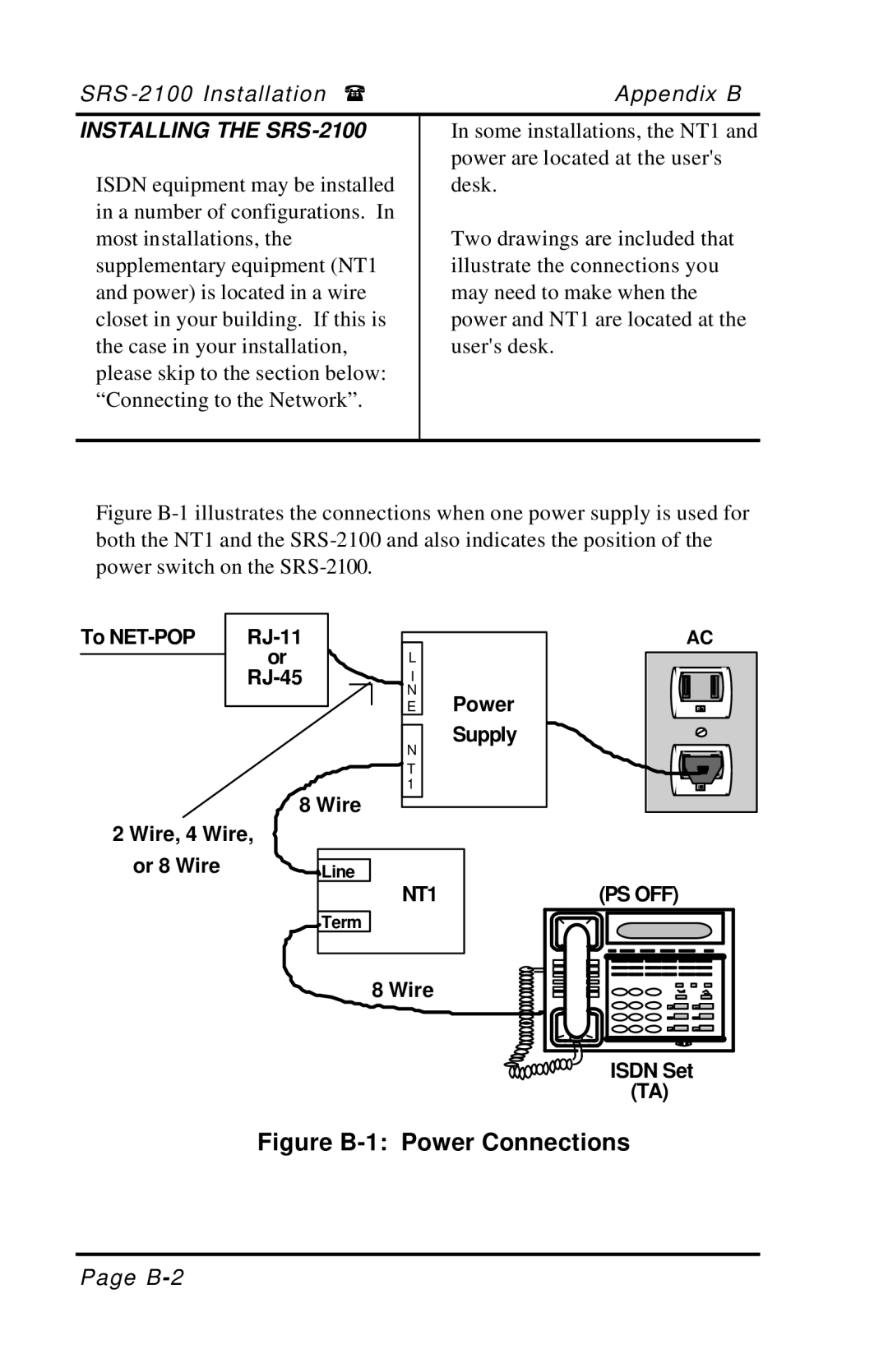
Figure B-1 illustrates the connections when one power supply is used for both the NT1 and the SRS-2100 and also indicates the position of the power switch on the SRS-2100.
To | |
| or |
| |
| |
|
|
8 Wire
2 Wire, 4 Wire,
L
I
N E
N
T 1
Power Supply
AC
or 8 Wire
Line
NT1
Term
8 Wire
(PS OFF)
ISDN Set |
(TA) |
Figure B-1: Power Connections
Page
