Managing hard drive space
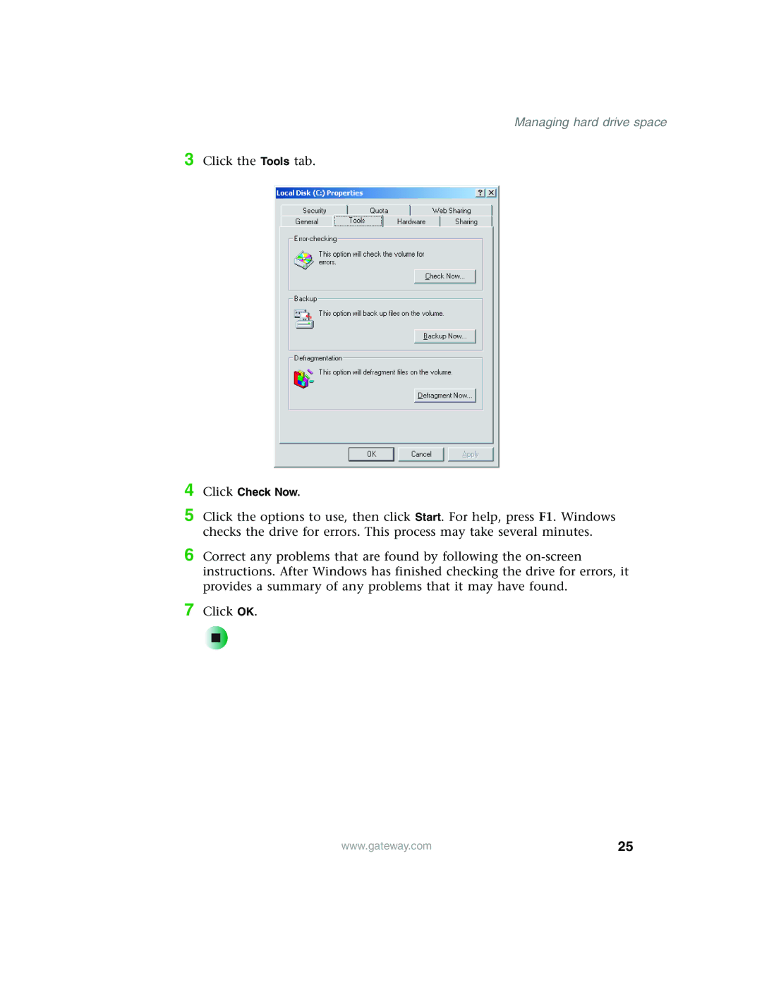
3 Click the Tools tab.
4 Click Check Now.
5 Click the options to use, then click Start. For help, press F1. Windows checks the drive for errors. This process may take several minutes.
6 Correct any problems that are found by following the
7 Click OK.
www.gateway.com | 25 |