Chapter 4: Installing Components
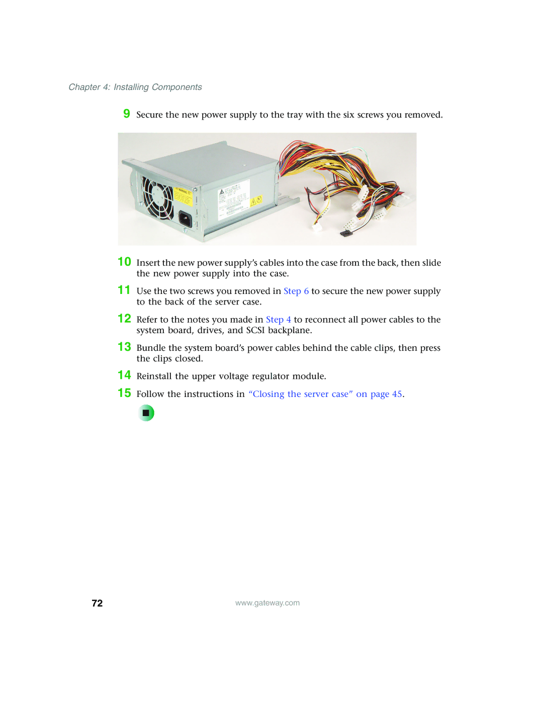
9 Secure the new power supply to the tray with the six screws you removed.
10 Insert the new power supply’s cables into the case from the back, then slide the new power supply into the case.
11 Use the two screws you removed in Step 6 to secure the new power supply to the back of the server case.
12 Refer to the notes you made in Step 4 to reconnect all power cables to the system board, drives, and SCSI backplane.
13 Bundle the system board’s power cables behind the cable clips, then press the clips closed.
14
15
Reinstall the upper voltage regulator module.
Follow the instructions in “Closing the server case” on page 45.
72 | www.gateway.com |