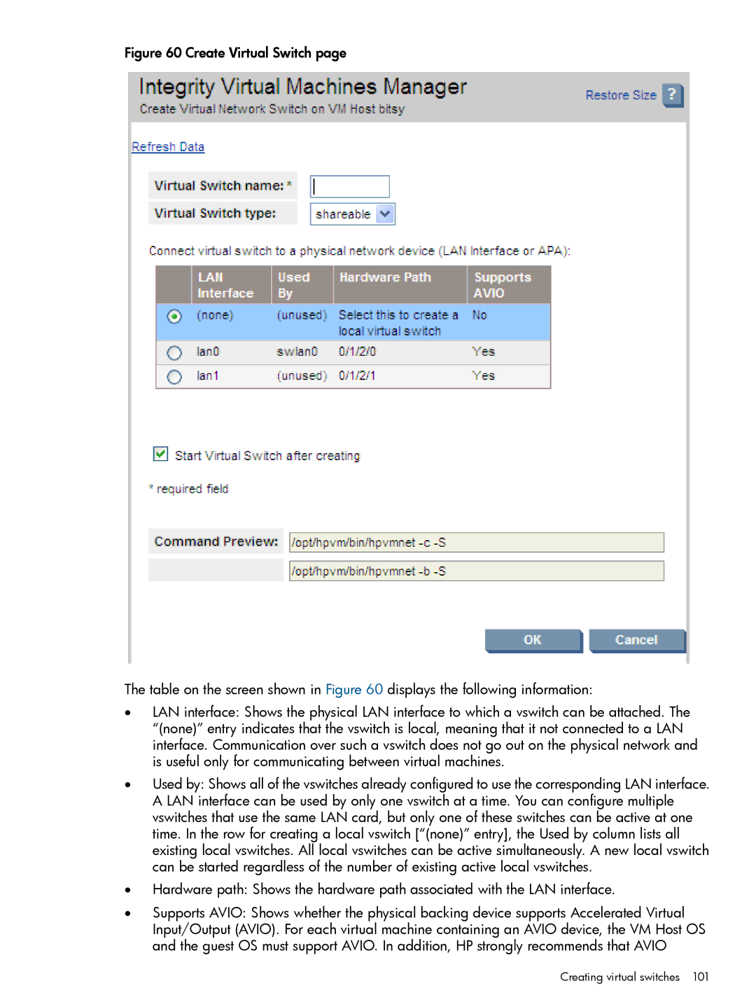
Figure 60 Create Virtual Switch page
The table on the screen shown in Figure 60 displays the following information:
•LAN interface: Shows the physical LAN interface to which a vswitch can be attached. The “(none)” entry indicates that the vswitch is local, meaning that it not connected to a LAN interface. Communication over such a vswitch does not go out on the physical network and is useful only for communicating between virtual machines.
•Used by: Shows all of the vswitches already configured to use the corresponding LAN interface. A LAN interface can be used by only one vswitch at a time. You can configure multiple vswitches that use the same LAN card, but only one of these switches can be active at one time. In the row for creating a local vswitch [“(none)” entry], the Used by column lists all existing local vswitches. All local vswitches can be active simultaneously. A new local vswitch can be started regardless of the number of existing active local vswitches.
•Hardware path: Shows the hardware path associated with the LAN interface.
•Supports AVIO: Shows whether the physical backing device supports Accelerated Virtual Input/Output (AVIO). For each virtual machine containing an AVIO device, the VM Host OS and the guest OS must support AVIO. In addition, HP strongly recommends that AVIO