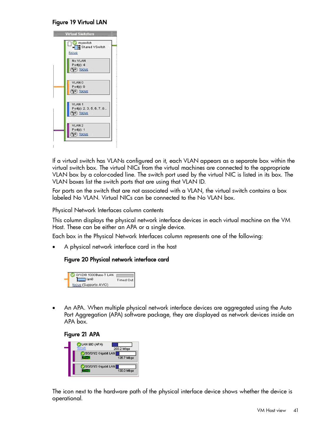
Figure 19 Virtual LAN
If a virtual switch has VLANs configured on it, each VLAN appears as a separate box within the virtual switch box. The virtual NICs from the virtual machines are connected to the appropriate VLAN box by a color-coded line. The switch port used by the virtual NIC is listed in its box. The VLAN boxes list the switch ports that are using that VLAN ID.
For ports on the switch that are not associated with a VLAN, the virtual switch contains a box labeled No VLAN. Virtual NICs can be connected to the No VLAN box.
Physical Network Interfaces column contents
This column displays the physical network interface devices in each virtual machine on the VM Host. These can be either an APA or a single device.
Each box in the Physical Network Interfaces column represents one of the following:
•A physical network interface card in the host Figure 20 Physical network interface card
•An APA. When multiple physical network interface devices are aggregated using the Auto Port Aggregation (APA) software package, they are displayed as network devices inside an APA box.
Figure 21 APA
The icon next to the hardware path of the physical interface device shows whether the device is operational.
VM Host view 41