I/O Panel
Removal
1. If | you have not already done so, remove the covers as described in “Cover |
page |
2. Disconnect the following cables from the system board:
Ÿ Serial Port 1
Ÿ Serial Port 2
Ÿ Tablet Port (2 connectors in some Model 140 systems)
ŸEthernet AUI
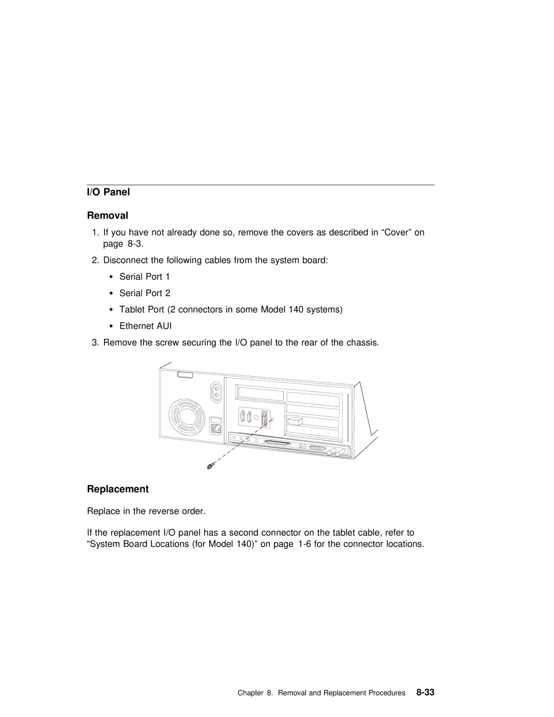
3.Remove the screw securing the I/O panel to the rear of the chassis.
Replacement
Replace in the reverse order.
If the replacement I/O panel has a second connector on the tablet cable, refe “System Board Locations (for Model 140)” on page
Chapter 8. Removal and Replacement
