Intel ZT 7102 manual System Architecture, Backplane Connections, Slot Connections

Models: ZT 7102

1 152
Download 152 pages 43.02 Kb
Page 18
Image 18

Intel® NetStructureTMZT 7102 Chassis Management Module

Hardware Specifications

2.2System Architecture

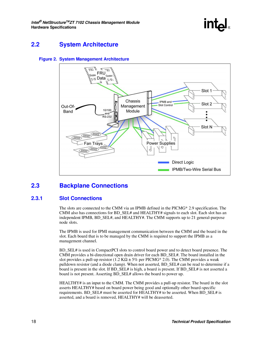
Figure 2. System Management Architecture

2.3Backplane Connections

2.3.1Slot Connections

The slots are connected to the CMM via an IPMB defined in the PICMG* 2.9 specification. The CMM also has connections for BD_SEL# and HEALTHY# signals to each slot. Each slot has an independent IPMB, BD_SEL#, and HEALTHY#. The CMM supports up to 21 general-purpose node slots.

The IPMB is used for IPMI management communication between the CMM and the board in the slot. Each board that is to be managed by the CMM is required to support the IPMB as a management channel.

BD_SEL# is used in CompactPCI slots to control board power and to detect board presence. The CMM provides a bi-directional open drain driver for each BD_SEL#. The board installed in the slot provides a pull-up resistor (1.2 K± 5% per PICMG* 2.0). The CMM provides a weak pulldown resistor (and a diode clamp). When not asserted, BD_SEL# can be read to determine if a board is present in the slot. If BD_SEL# is high, a board is present. If BD_SEL# is not asserted a board is not present. Asserting BD_SEL# allows the board to power up.

HEALTHY# is an input to the CMM. The CMM provides a pull-up resistor. The board in the slot asserts HEALTHY# based on board power being good and optionally other board-specific requirements. BD_SEL# must be asserted for HEALTHY# to be asserted. When BD_SEL# is asserted, and a board is removed, HEALTHY# will be deasserted.

18

Technical Product Specification

Page 18
Image 18
Intel ZT 7102 manual System Architecture, Backplane Connections, Slot Connections