Intel® NetStructureTMZT 7102 Chassis Management Module
Hardware Specifications
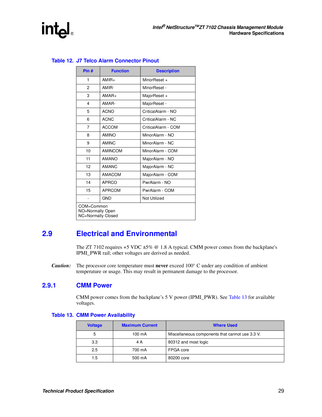
Table 12. J7 Telco Alarm Connector Pinout
Pin # | Function | Description |
|
|
|
1 | AMIR+ | MinorReset + |
|
|
|
2 | AMIR- | MinorReset - |
|
|
|
3 | AMAR+ | MajorReset + |
|
|
|
4 | AMAR- | MajorReset - |
|
|
|
5 | ACNO | CriticalAlarm - NO |
|
|
|
6 | ACNC | CriticalAlarm - NC |
|
|
|
7 | ACCOM | CriticalAlarm - COM |
|
|
|
8 | AMINO | MinorAlarm - NO |
|
|
|
9 | AMINC | MinorAlarm - NC |
|
|
|
10 | AMINCOM | MinorAlarm - COM |
|
|
|
11 | AMANO | MajorAlarm - NO |
|
|
|
12 | AMANC | MajorAlarm - NC |
|
|
|
13 | AMACOM | MajorAlarm - COM |
|
|
|
14 | APRCO | PwrAlarm - NO |
|
|
|
15 | APRCOM | PwrAlarm - COM |
|
|
|
- | GND | Not Utilized |
|
|
|
COM=Common
NO=Normally Open
NC=Normally Closed
2.9Electrical and Environmental
The ZT 7102 requires +5 VDC ±5% @ 1.8 A typical. CMM power comes from the backplane's IPMI_PWR rail; other voltages are derived as needed.
Caution: The processor core temperature must never exceed 100° C under any condition of ambient temperature or usage. This may result in permanent damage to the processor.
2.9.1CMM Power
CMM power comes from the backplane’s 5 V power (IPMI_PWR). See Table 13 for available voltages.
Table 13. CMM Power Availability
Voltage | Maximum Current | Where Used |
|
|
|
5 | 100 mA | Miscellaneous components that cannot use 3.3 V. |
|
|
|
3.3 | 4 A | 80312 and most logic |
|
|
|
2.5 | 700 mA | FPGA core |
|
|
|
1.5 | 500 mA | 80200 core |
|
|
|
Technical Product Specification | 29 |