Intel® NetStructureTMZT 7102 Chassis Management Module
Hardware Specifications
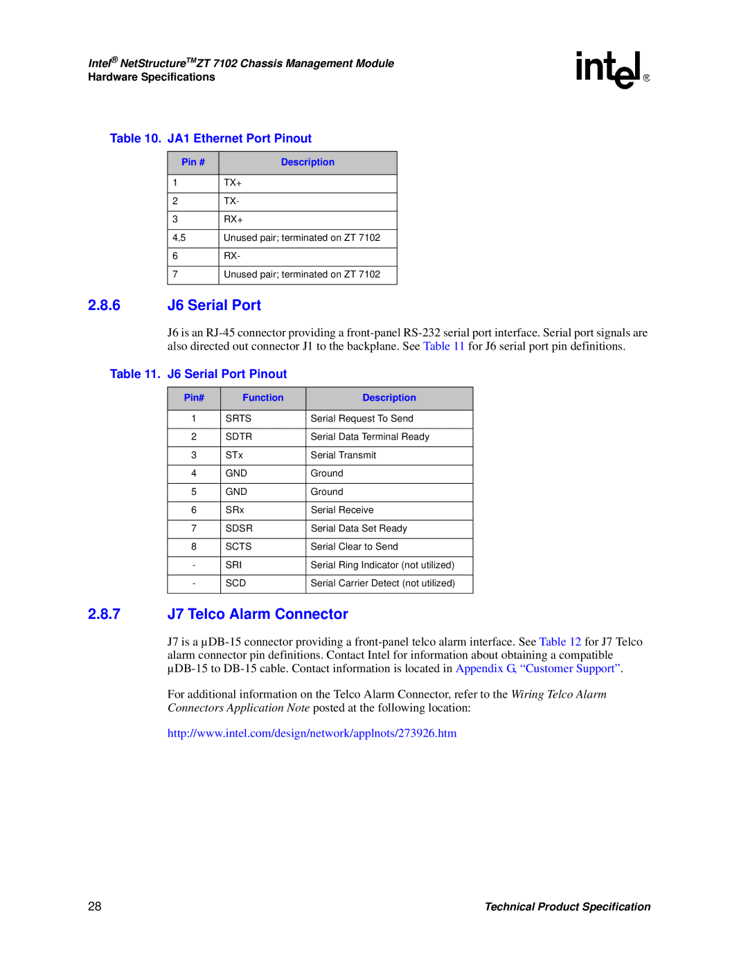
Table 10. JA1 Ethernet Port Pinout
Pin # | Description |
|
|
1TX+
2TX-
3RX+
4,5 | Unused pair; terminated on ZT 7102 |
6RX-
7Unused pair; terminated on ZT 7102
2.8.6J6 Serial Port
J6 is an
Table 11. J6 Serial Port Pinout
Pin# | Function | Description |
|
|
|
1 | SRTS | Serial Request To Send |
|
|
|
2 | SDTR | Serial Data Terminal Ready |
|
|
|
3 | STx | Serial Transmit |
|
|
|
4 | GND | Ground |
|
|
|
5 | GND | Ground |
|
|
|
6 | SRx | Serial Receive |
|
|
|
7 | SDSR | Serial Data Set Ready |
|
|
|
8 | SCTS | Serial Clear to Send |
|
|
|
- | SRI | Serial Ring Indicator (not utilized) |
|
|
|
- | SCD | Serial Carrier Detect (not utilized) |
|
|
|
2.8.7J7 Telco Alarm Connector
J7 is a
For additional information on the Telco Alarm Connector, refer to the Wiring Telco Alarm Connectors Application Note posted at the following location:
http://www.intel.com/design/network/applnots/273926.htm
28 | Technical Product Specification |