Intel® NetStructureTMZT 7102 Chassis Management Module
Hardware Specifications
2.9.6DC Operating Characteristics
Table 15. DC Operating Characteristics
Signal |
| Range |
|
|
|
Supply Voltage, VCC | 4.85 V minimum to 5.25 | V maximum |
| 1.8 A average (with 733 | MHz processor and 32 Mbyte of SDRAM. Peak |
Supply Current, ICC | (short duration) power supply current may be significantly higher (up to | |
| 50%) and varies depending upon the application. | |
|
|
|
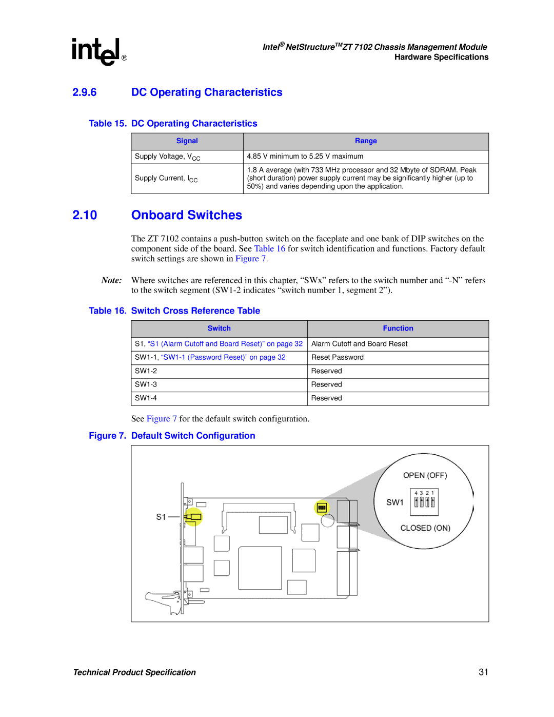
2.10Onboard Switches
The ZT 7102 contains a
Note: Where switches are referenced in this chapter, “SWx” refers to the switch number and
Table 16. Switch Cross Reference Table
Switch | Function |
|
|
S1, “S1 (Alarm Cutoff and Board Reset)” on page 32 | Alarm Cutoff and Board Reset |
|
|
Reset Password | |
|
|
Reserved | |
|
|
Reserved | |
|
|
Reserved | |
|
|
See Figure 7 for the default switch configuration.
Figure 7. Default Switch Configuration
Technical Product Specification | 31 |