Intel® NetStructureTMZT 7102 Chassis Management Module
Hardware Specifications
2.6.1Faceplate Features
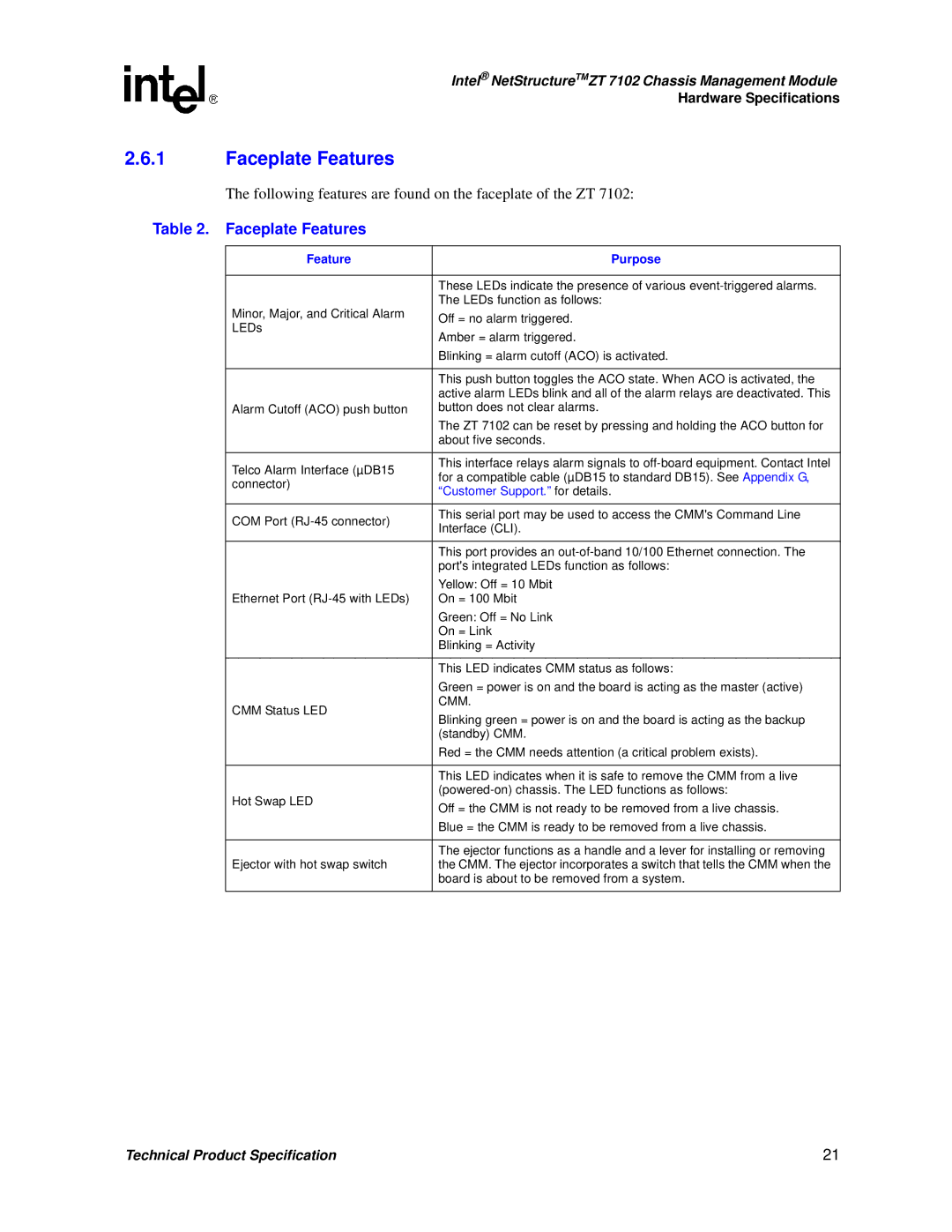
The following features are found on the faceplate of the ZT 7102:
Table 2. Faceplate Features
Feature | Purpose | |
|
| |
| These LEDs indicate the presence of various | |
| The LEDs function as follows: | |
Minor, Major, and Critical Alarm | Off = no alarm triggered. | |
LEDs | ||
Amber = alarm triggered. | ||
| ||
| Blinking = alarm cutoff (ACO) is activated. | |
|
| |
| This push button toggles the ACO state. When ACO is activated, the | |
| active alarm LEDs blink and all of the alarm relays are deactivated. This | |
Alarm Cutoff (ACO) push button | button does not clear alarms. | |
| The ZT 7102 can be reset by pressing and holding the ACO button for | |
| about five seconds. | |
|
| |
Telco Alarm Interface (µDB15 | This interface relays alarm signals to | |
for a compatible cable (µDB15 to standard DB15). See Appendix G, | ||
connector) | ||
“Customer Support.for” details. | ||
| ||
|
| |
COM Port | This serial port may be used to access the CMM's Command Line | |
Interface (CLI). | ||
| ||
|
| |
| This port provides an | |
| port's integrated LEDs function as follows: | |
| Yellow: Off = 10 Mbit | |
Ethernet Port | On = 100 Mbit | |
| Green: Off = No Link | |
| On = Link | |
| Blinking = Activity | |
|
| |
| This LED indicates CMM status as follows: | |
| Green = power is on and the board is acting as the master (active) | |
CMM Status LED | CMM. | |
Blinking green = power is on and the board is acting as the backup | ||
| ||
| (standby) CMM. | |
| Red = the CMM needs attention (a critical problem exists). | |
|
| |
| This LED indicates when it is safe to remove the CMM from a live | |
Hot Swap LED | ||
Off = the CMM is not ready to be removed from a live chassis. | ||
| ||
| Blue = the CMM is ready to be removed from a live chassis. | |
|
| |
| The ejector functions as a handle and a lever for installing or removing | |
Ejector with hot swap switch | the CMM. The ejector incorporates a switch that tells the CMM when the | |
| board is about to be removed from a system. | |
|
|
Technical Product Specification | 21 |
