Intel® NetStructureTMZT 7102 Chassis Management Module
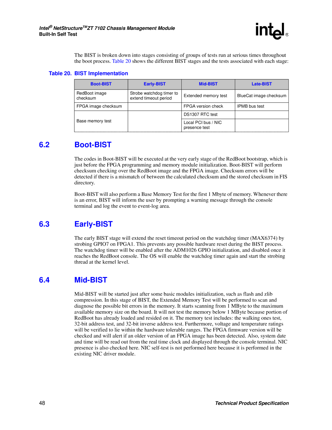
The BIST is broken down into stages consisting of groups of tests run at serious times throughout the boot process. Table 20 shows the different BIST stages and the tests associated with each stage:
Table 20. BIST Implementation
|
|
|
| |
|
|
|
| |
RedBoot image | Strobe watchdog timer to | Extended memory test | BlueCat image checksum | |
checksum | extend timeout period | |||
|
| |||
|
|
|
| |
FPGA image checksum |
| FPGA version check | IPMB bus test | |
|
|
|
| |
|
| DS1307 RTC test |
| |
Base memory test |
|
|
| |
| Local PCI bus / NIC |
| ||
|
|
| ||
|
| presence test |
| |
|
|
|
|
6.2Boot-BIST
The codes in
6.3Early-BIST
The early BIST stage will extend the reset timeout period on the watchdog timer (MAX6374) by strobing GPIO7 on FPGA1. This prevents any possible hardware reset during the BIST process. The watchdog timer will be enabled after the ADM1026 GPIO initialization, and disabled once it reaches the RedBoot console. The OS will enable the watchdog timer again and start the strobing thread at the kernel level.
6.4Mid-BIST
48 | Technical Product Specification |
