|
| 4: Configuration Using Web Manager |
|
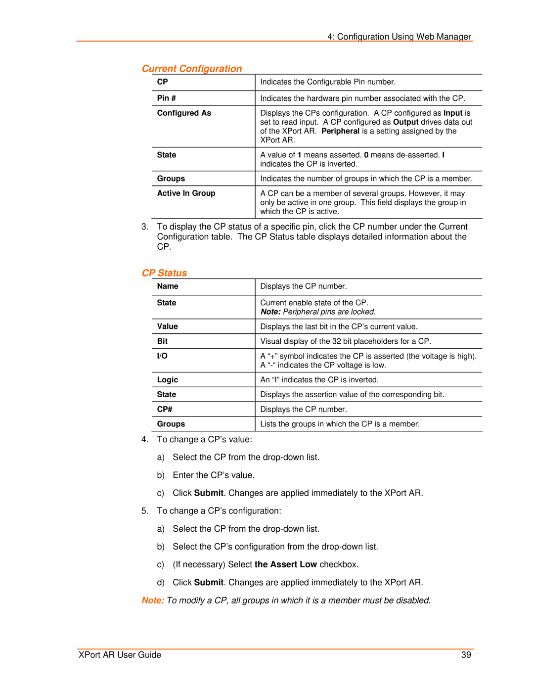
Current Configuration |
|
| |
| CP | Indicates the Configurable Pin number. |
|
|
|
|
|
| Pin # | Indicates the hardware pin number associated with the CP. |
|
|
|
|
|
| Configured As | Displays the CPs configuration. A CP configured as Input is |
|
|
| set to read input. A CP configured as Output drives data out |
|
|
| of the XPort AR. Peripheral is a setting assigned by the |
|
|
| XPort AR. |
|
|
|
|
|
| State | A value of 1 means asserted. 0 means |
|
|
| indicates the CP is inverted. |
|
|
|
|
|
| Groups | Indicates the number of groups in which the CP is a member. |
|
|
|
|
|
| Active In Group | A CP can be a member of several groups. However, it may |
|
|
| only be active in one group. This field displays the group in |
|
|
| which the CP is active. |
|
|
|
|
|
3.To display the CP status of a specific pin, click the CP number under the Current Configuration table. The CP Status table displays detailed information about the CP.
CP Status
Name
State
Value
Bit
I/O
Logic
State
CP#
Groups
Displays the CP number.
Current enable state of the CP.
Note: Peripheral pins are locked.
Displays the last bit in the CP’s current value.
Visual display of the 32 bit placeholders for a CP.
A “+” symbol indicates the CP is asserted (the voltage is high). A
An “I” indicates the CP is inverted.
Displays the assertion value of the corresponding bit.
Displays the CP number.
Lists the groups in which the CP is a member.
4.To change a CP’s value:
a)Select the CP from the
b)Enter the CP’s value.
c)Click Submit. Changes are applied immediately to the XPort AR.
5.To change a CP’s configuration:
a)Select the CP from the
b)Select the CP’s configuration from the
c)(If necessary) Select the Assert Low checkbox.
d)Click Submit. Changes are applied immediately to the XPort AR.
Note: To modify a CP, all groups in which it is a member must be disabled.
XPort AR User Guide | 39 |