|
| 4: Configuration Using Web Manager |
|
|
|
|
|
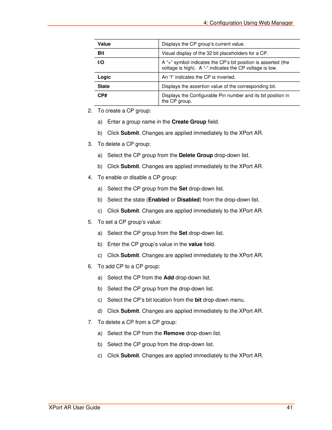
| Value | Displays the CP group’s current value. |
|
|
|
|
|
| Bit | Visual display of the 32 bit placeholders for a CP. |
|
|
|
|
|
| I/O | A “+” symbol indicates the CP’s bit position is asserted (the |
|
|
| voltage is high). A |
|
| Logic | An “I” indicates the CP is inverted. |
|
|
|
|
|
| State | Displays the assertion value of the corresponding bit. |
|
|
|
|
|
| CP# | Displays the Configurable Pin number and its bit position in |
|
|
| the CP group. |
|
|
|
|
|
2.To create a CP group:
a)Enter a group name in the Create Group field.
b)Click Submit. Changes are applied immediately to the XPort AR.
3.To delete a CP group:
a)Select the CP group from the Delete Group
b)Click Submit. Changes are applied immediately to the XPort AR.
4.To enable or disable a CP group:
a)Select the CP group from the Set
b)Select the state (Enabled or Disabled) from the
c)Click Submit. Changes are applied immediately to the XPort AR.
5.To set a CP group’s value:
a)Select the CP group from the Set
b)Enter the CP group’s value in the value field.
c)Click Submit. Changes are applied immediately to the XPort AR.
6.To add CP to a CP group:
a)Select the CP from the Add
b)Select the CP group from the
c)Select the CP’s bit location from the bit
d)Click Submit. Changes are applied immediately to the XPort AR.
7.To delete a CP from a CP group:
a)Select the CP from the Remove
b)Select the CP group from the
c)Click Submit. Changes are applied immediately to the XPort AR.
XPort AR User Guide | 41 |