2TQFWEV/CPWCN
WPG
Page
Page
6CDNGQH%QPVGPVU1-1
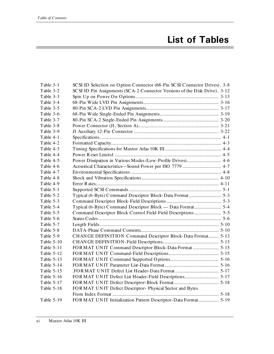
Table of Contents
Mode Select 6 Command 15h
Error Recovery
HOT PLUGGING/REMOVAL and Insertion of Scsi Devices
Maxtor Atlas 10K
Drive Packing Assembly
J1 Auxiliary 12-Pin Connector
Power Dissipation in Various Modes Low-Profile Drives
Format Unit Initialization Pattern Descriptor-Data Format
Unit Attention Condition Read-Write Error Recovery Page-Page
Verify Error Recovery Page-Field Descriptions
Saved Training Configuration Subpage 02h
Persistent Reservation in Command-Field Descriptions
Disconnect-Reconnect-Field Descriptions
118 Persistent Reservation OUT Command
Command-Data Format 114
Command-Field Description 115
115 Persistent Reservation in Read Reservations
129
Reserve 10 Command-Field Descriptions 156
157
165
Table A-2
Xvii Maxtor Atlas 10K
Maxtor Atlas 10K III
Error correcting code
Application-specific integrated circuit
Least significant bit
Low voltage differential Scsi
Mode Select
About This Manual
Ultra160 SCSI, Ultra2, Ultra Scsi 68-pin Wide 16-bit
Ultra160 SCSI, Ultra2, Ultra Scsi 80-pin SCA-2 16-bit
Ultra320 SCSI, Ultra2, Ultra Scsi 68-pin Wide 16-bit
Ultra320 SCSI, Ultra2, Ultra Scsi 80-pin SCA-2 16-bit
General Description
General Description
General Description
#76+10PCBA
Installation
Dimensions for the Maxtor Atlas 10K III Hard Disk Drives
Pin Wide Scsi Pin SCA- Scsi
Remove the drive from the packing assembly
Drive Packing Assembly
Kiwtg
#76+10
Fault GND Busy
Jumper Locations on the 68-Pin Wide Scsi Drive PCB
ID bit 0, at Pin 8, is the Least Significant Bit
6CDNG
Installation
Termination Power Circuitry
Spin Up Activity LED displays
60±0.50
Option 1 Spin up occurs immediately when power is applied
Spin Up on Power On Options
Open Ground Reserved
J7 Jumper Location on the 80-Pin SCA PCB
Kiwtg
+DB +DB P1
+C/D
+I/O +DB
12V
+DB +I/O REQ
+SEL MSG +MSG RST +RST ACK +ACK
+BSY ATN +ATN DB P0 +DB P0
= Short pin = Long pin
+DB DB P1 +DB P1
Scsi ID
DB P
BSY
SEL
REQ
= Short pin, L = Long pin
Power Connector J1, Section a
AMP P/N
J1 Auxiliary 12-Pin Connector
Mounting Dimensions Maxtor Atlas 10K III Drives
Following subsections
Mounting Screw Clearance for Maxtor Atlas 10K III Drive
Lengthwise Airflow Cooling
Kiwtg
Crosswise Airflow Cooling
52%++%#6+1057//#4Specifications
247,128
≤ .73 ms write Sequential Cylinder Switch Ms read
DensityMaximum effective areal
Ms write Random Average Seek Ms typical Read
Ms typical Write
Formatted Capacity
Number of 512-byte
Timing Specifications for Maxtor Atlas 10K
Temperature, nominal supply
Typical
Track of the same cylinder
Power Reset Limits1
#614#6.#5±10%-+++$
Power Dissipation in Various Modes Low-Profile Drives
+50.9 -$
Acoustical Characteristics-Sound Power per ISO
’s defined nominal position
18.4 Bels typical 73.4
All dimensions are exclusive of any optional faceplate
Environmental Specifications
010
+.%641/#06+%4+5WUEGRVKDKNKV Volts/meter @ 100%10&+6+105 MHz
Shock and Vibration Specifications
At ambient temperature Unrecoverable errors
Error Rates
4414
Specifications
Supported Scsi Commands
Mode Sense
Format Unit
Inquiry
Send Diagnostic
Persistent Reservation OUT
Read Capacity
Read Defect Data
MSB
LBA
$VG
5contains a description of the CDB control field
Naca
Guetkrvkqp
These bits must be
Status Codes
Scsi Description
Scsi Description
Scsi Description
Length Fields
Definition
OUT
Data
Reassign
BL CKS
Diagn Stic
Data 5
Byte Transfer LBA Tag Must be EDC ECC
Data 1 logical sector
Change Definition Command Descriptor Block-Data Format
SCSI-1
SCSI-2 SCSI-3
Scsi Description
36#/-836
Format Unit Command Supported Options
013
Bytes or eight bytes in length
Format Unit Parameter List-Data Format
Format Unit Defect List Header-Data Format
FOV Dpry Dcrt Stpf DSP
Immed Defect List Length
$KVTable
Defect as shown in Table
Format Unit Defect Descriptor-Block Format
Format Unit Defect Descriptor- Physical Sector and Bytes
Format Unit Initialization Pattern Descriptor-Data Format
Format Unit Initialization Pattern Type
Condition status. The sense key is set to Illegal REQUEST,
Sense Code is set to Invalid Field in Parameter List
Operation Code 12h Reserved CmdDt
Evpd
Code or Operation Code
Allocation Length Control
Standard Inquiry Data Page-Data Format
Ackqreqq
QAS
Supported Vital Product Data Pages -Data Format
Reserved Length = 08h Supported Page List
Firmware Revision
Maxtor Manufacturing Number C4h
Unit Serial Number Page-Data Format
Unit Serial
Number Peripheral Device Type = 000h
Implemented Operating Definition Page-Data Format
That the corresponding operating definition Can be saved
Direct Access Device Code 82h
Ascii Implemented Operating Definition Page Data Format
Peripheral Qualifier
$VG
Device Identification Page Data Format
Device Identification Page-Field Description
Scsi Description
Firmware Revision Page-Data Format
Table Build5- Date35
Length = 24h Full Firmware Version Blank Fill e.g., T382
Time Blank Fill e.g., Jan 19 1999
Value in the Bytes 4 19 field is assigned by Maxtor Corpo
Length = 10h Spaces or Maxtor-Unique Information
Negotiated Rate Information Page-Data Format
AIP Aipd Aipce TWE Parl Fair Sync
Negotiated Rate Information Page-Field Descriptions
Command Support Data Page-Data Format
$BitVG
LSB
Type of support that the disk
Command Support Data Page Command or Operation Codes
Verify FFF03
FFFF03
Data FFFF03
3BE Ffff E00FFF
LOG Select Command Descriptor Block-Data Format
Operation Code 4Ch Reserved
PCR
Reserved Parameter List Length Control
Disk Drive Log Pages
Operation Code 4Dh Reserved
PPC
Code
Parameter Pointer Allocation Length Control
LOG Sense Log Page Format-Data Format
Allocation length for the page minus
TSD
TMC Lbin
Generic Log Parameter-Field Descriptions
DU, DS, TSD, ETC, TMC and LP fields are collectively re
TMC
Mode Select 6 Command Descriptor Block-Data Format
Select operation and does not save any pages. When SP = 1,
Operation Code 15h Reserved
Parameter Length List Control
Initiator-Changeable Mode Pages
Caching Cache policy 0Ah1 Control Mode
2CIG00h%QFG
Unit Attention report
Mode Page Types
Mode Parameter List-Data Format
Initiator-accessible logical blocks to the amount specified
$VG$KV
Mode Sense command
Categories of Changeable Pages
Unit Attention Condition
DUA
Read-Write Error Recovery Page-Page
Tablecountered5-65
Awre
EER PER
Recovery
Cases where error recovery is invoked and successful
Disconnect-Reconnect
Maxtor Atlas 10K IIIUGTXGFHQTVJG5%5+%%5QRGTCVKPIOQFG
Emdp
Dtdc
Enable Modify Data Pointer
Ity arbitration when beginning the interconnect tenancy
Tion conditions for example, Sdtr received, error, etc
When a disconnect is permitted. These are as follows
Verify Error Recovery Page-Page
Sense command, since the page is savable
EER PER DTE DCR
Field descriptions are described in -70and -71respectively
Caching Page-Page
WCE
Lbcss
Pre-fetch Cache as a result of one Read command
A non-volatile, vendor-specific location. Bit reserved with
Blocks for each of the respective types of prefetch
Retention Priority Demand Write
FSW
DRA
Vendor-Specific bits Number
14h Ignored by the drive Segments
Control Mode Page-Page 0Ah
Code 0Ah
Queue Algorithm Modifier Reserved
Raerp
Control Mode Page-Field Descriptions Page 0Ah
Ready AER Permission.0QVUWR+IPTGFRQTVGFDDVJVJDVJGFTKXG
RAC
Uaaerp
Notch and Partition Page-Page 0Ch
Length 16h
Notch and Partition Page-Field Descriptions Page 0Ch
Synchronous Transfer Timeout
Port Control Page Short Format
Length 06h Reserved Protocol Identifier 1h
Port Control Page Long Format
Subpage Code
Reserved Protocol Identifier 1h
Power Condition Page-Page 1Ah
Reserved IdlEnb Sby Idle Timer Standby Timer
Power Condition Page-Field Descriptions Page 1Ah
With the Mode Select command
Information Exceptions Control Page-Page 1Ch
MSBTable5-80
Ewasc
Mrie MSB
Mrie
Codes Used by the Mrie Field
Report an informational exception condition
Exception condition
Table Fault
QuietSeekMode
Maxtor-Unique Page-Data Format Page 39h
$KV
Maxtor-Unique Page-Field Descriptions Page 39h
Scam
Sssie
PXM
ISN
IWN
Asdp
Guetkrvkqp
Dewg
Ssso
Eamnr
#UPEJTQPQWUTo start AIP+PHQTOCVKQP2TQVGEVKQP#+2
Mode Select 10 Command Descriptor Block-Data Format
Parameter List Length Control
Medium Type Device-Specific Parameter
Density Code
Mode Parameter Block Descriptor-Field Descriptions
Medium characteristics specified
By the block descriptor
DBD
Reserved Code
Returns only the requested pages
Mode Parameter Header-Field Descriptions
5K\G24DVGU
Rigid Disk Geometry Total cylinder head Rotational speed
Transfer capabilities
Format Device Page-Page
Hsec RMB
Non-volatile vendor specific location
For 18 GB For 36 GB For 73 GB
Drive does not have any alternate tracks
Zone
Rigid Disk Geometry Page-Page
Rigid Disk Geometry
Page4
RPL
Storage arrays. The modes are 00b Disabled 10b Master
URKPFNGUPEJTQPK\CVKQP
$VG 0$KV
Margin Control Subpage 01h
For the current Nexus are reported
Negotiated Settings Subpage 03h
Bus Mode
101High
Mode
Maxtor-Unique Caching Page-Page 38h
Rsv’d Code 38h Length 0Eh Reserved Cache Table Size
Mode Sense 10 Command Descriptor Block-Data Format
105
104
106
Mode Parameter Header & Block Descriptor-Field Descriptions
Accessible logical blocks to the amount specified
107
Reserved Service Action
108
Persistent Reservation in Command-Field Descriptions
110
Read Keys Parameters-Data Format
111
112
Read Keys Parameters-Field Descriptions
Described in -112and -113respectively
Read Reservations Parameters-Field Descriptions
11415
Scope-Specific Address
Scope Type
Parameters
As Additional Reservations Allowed in the table
Ment Persistent Reservation OUT
Reservation OUT
Persistent Reservation Type Codes and Their Meanings
Persistent reservations
LU EX
Shared Access
Reserved Service Action Scope Type
118
Parameter List Length 18h
Persistent Reservation OUT Command-Field Descriptions
Vation OUT
Tent Reservation OUT
120
0COG
QFG04h
Pre0COG-empt
QFG05h
Clear
Sults in a reservation conflict
121
Illustrated in -122and defined in -123.Each of the fields
Persistent Reservation OUT Parameter List-Data Format
Aptpl
Behavior in the event of a power loss
To Invalid Field in Parameter List
Register Reserve
Release
Pre-empt
Pre-empt & Clear
Read 6 Command-Data Format
Ferred. Any other value indicates the number
Logical blocks that will be transferred
Using its normal Logical Read Unit policies
Operation Code 28h Reserved
DPO FUA
Reserved RelAdr Logical Block Address
Read Buffer Command-Data Format
Reserved Mode Buffer ID Buffer Offset
Read Buffer Command-Field Descriptions
0010b
Multiple
Read Capacity Command-Data Format
Read Capacity Command-Field Descriptions
132
Description in -132for a description of these data fields
Read Defect Data 10 Command-Data Format
9Table5-134
Reserved Plist Glist Defect List Format
Read Defect Data 10 Command-Field DescriptionREAD Defect
135
$ 4VG -$ 7KV
Defect Descriptor-Block Format
Defect List Header -Data Format
Reserved Plist Glist Defect List Format Defect List Length
Defect List
Read Defect Data 12 Command-Data Format
11Table5-140
Plist Glist Defect List Format Reserved
Read Defect Data 12 Command-Field Description
142
Are returned in ascending order
Normal user space
Defect List Header-Data Format
Mary Defect List
Read Long Command Descriptor Block-Data Format
Read Long Command Descriptor Block-Field Descriptions
Read Long Command-Returned Data
148
514 EDC 8 Bits
Operation Code E8h
Skip Mask Length
Reserved Flag Link
Reassign Blocks Command Descriptor Block-Data Format
Reassign Blocks Defect List Header-Data Format
Operation Code 07h
154
Reassign Blocks Defect Descriptor-Data Format
157
$VG0$KV 155
PCV
Code Value Allocation Length Reserved Control
Maxtor Atlas 10K 123
159
Translate Address Page-Data Format
Rarea ALT
Translate Address Page-Field Descriptions
Rarea
Altsec
Alttrk
Release 6 Command Descriptor Block-Data Format
Release 6 Command -Field Descriptions
Release 10 Command Descriptor Block-Data Format
163
Release 10 Command Field Descriptions
164
Service Action 05h
168
167
Report Device Identifier Parameter List-Data Format
Report Device Identifier Parameter List-Field Descriptions
Report Luns Command Descriptor Block-Data Format
170
LUN Reporting Parameter List -Data Format
169
Request Sense Command Descriptor Block-Data Format
Operation Code 03h Reserved Allocation Length Control
Inquiry
Scsi Description
Sense Data Format for Error Code 70h or 71h-Data Format
174
EOM ILI
Sksv
FRU
Supported Sense Keys
Sense Key Information Field Contents
0QVG+.+YKNNDGUGV
Guucig
0x5DTable
Guucig
Gcpkpi
Cvgiqt
QFG
Maxtor Atlas 10K 143
Ecspkadr ERR
Maxtor Atlas 10K 145
Recal Ecrclfail in Peslin
QFG
QFG
Maxtor Atlas 10K 149
5GPUG
Maxtor Atlas 10K 151
Sense-Key Specific Field Contents
Error
$VG 15$KV SKSVTable C/D5-179
Ered
Data is contained in Table
184Table175-183
BPV
90 Medium Error or Recovered Error Sense Key Retry Count
Sksvkgnf
Retry
Number of times an I/O operation was retried
Reserve 6 Command Descriptor Block-Data Format
Reserve 6 Command-Field Descriptions
187
186
Reserve 10 Command Descriptor Block-Data Format
Operation Code 56h Reserved 3rdPty
193
Parameter list has the format shown in Table
190
191
Rezero Unit Command Descriptor Block-Data Format
194
Seek 6 Command Descriptor Block-Data Format
195
Reserved Logical Block Address
Seek 10 Command Descriptor Block-Data Format
196
Reserved Control
Test routine in the background mode
Tine in the foreground mode
Test routine in the foreground mode
011b Reserved
Kgnf
Supported Diagnostic Page List-Data Format
Length 00h
200
SET Device Identifier Command Descriptor Block-Data Format
TableKGNF5-203
SET Device Identifier Parameter List-Data Format
SET Device Identifier Parameter List-Field Descriptions
Power Conditions Reserved LoEj Start Control
205
Operation Code 1Bh Reserved Immed
Synchronize Cache Command Descriptor Block-Data Format
208respectively
Table Block5- Ad207
Number of Blocks Control
Test Unit Ready Command Descriptor Block-Data Format
$VG$KV
Verify Command Descriptor Block-Data Format
DPO
Write 6 Command Descriptor Block-Data Format
Write 10 Command Descriptor Block-Data Format
Operation Code 2Ah Reserved
Drives cache
Write and Verify Command Descriptor Block-Data Format
216
Operation Code 2Eh Reserved
Logical Block Address space
Write Buffer Command Descriptor Block-Data Format
Reserved Mode Buffer ID Buffer Offset Parameter List Length
218
Write Buffer Command-Field Descriptions
Write Long Command Descriptor Block-Data Format
220
Operation Code 3Fh Reserved RelAdr Logical Block Address
Write Same Command Descriptor Block-Data Format
LBdata
Write Skip Mask Command Descriptor Block-Data Format
TableLength5-224
225
Operation
Scsi Description
Drives when shipped
Feature Descriptions
Maxtor Atlas 10K III
Number, before it will read or write the data
For the drive to return data from the wrong head
Feature Descriptions
Feature Descriptions
Feature Descriptions
Attempted without host intervention
Correct track
Feature Descriptions
Continues to monitor the Diffsens signal. If
Detects the change and prese ts mode change
Operating mode of the interface switches
Might occur if a
ST and DT CLocking
Feature Descriptions
Maxtor Atlas 10K III
Feature Descriptions
Feature Descriptions
Feature Descriptions
SCSI-2/SCSI- Equivalent Terminology
Abort
Simple queue tag
SCSI-3 Quick Reference Commands
Seek
Linked Command Complete w/FLAG
SCSI-3 Quick Reference Messages
Ascii Implemented Operating Def Inition
UI%QFG 06 *GZ
Appendix a
Good 5VCVWU%QFGU
SCSI-3 Quick Reference Sense Keys
Appendix a
Transfer Period Factor Field Values When Parl =
Guetkrvkqp
OUT phases to transfer data
Use DT Data in and DT Data OUT phases with data group
Use DT Data in and DT Data OUT phases with information unit
Transfers
Maxtor Atlas 10K III 18/36/73 GB Ultra160 Scsi
Glossary
Drive Short form of disk drive
4Maxtor Atlas 10K III 18/36/73 GB Ultra160 Scsi
Basic configurations. See also low-level formatting
LOW-VOLTAGE Differential LVD
Glossary
8Maxtor Atlas 10K III 18/36/73 GB Ultra160 Scsi
Glossary
10Maxtor Atlas 10K III 18/36/73 GB Ultra160 Scsi
Glossary
12Maxtor Atlas 10K III 18/36/73 GB Ultra160 Scsi
Allocation Length 5-10,5-38,5-122, 5- 131, 5-132,5-134
Defect List Length 5-16,5-17,5-113, 5- 116 Defect Lists
25,5-26
Formatted capacity 4-1,4-3full stroke General2-1
138,5-153
New Operating Definition 5-13NO Sense 5-7,5-137
158
167
Synchronous Data Transfer
6Maxtor Atlas 10K