7.2.4Calibrating Tool Offset Sensor
Calibrating the Sensor to the Coordinate System of Chuck
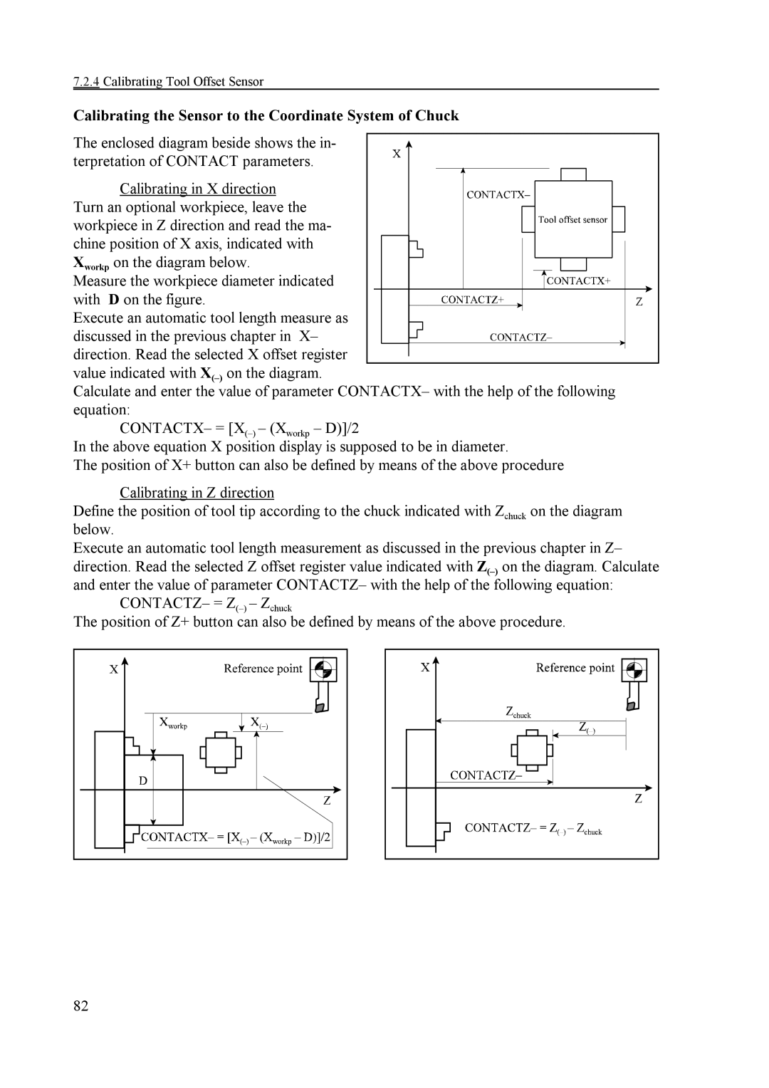
The enclosed diagram beside shows the in- terpretation of CONTACT parameters.
Calibrating in X direction Turn an optional workpiece, leave the
workpiece in Z direction and read the ma- chine position of X axis, indicated with
Xworkp on the diagram below. Measure the workpiece diameter indicated
with D on the figure. Execute an automatic tool length measure as
discussed in the previous chapter in X– direction. Read the selected X offset register
value indicated with
Calculate and enter the value of parameter CONTACTX– with the help of the following equation:
CONTACTX– =
In the above equation X position display is supposed to be in diameter.
The position of X+ button can also be defined by means of the above procedure
Calibrating in Z direction
Define the position of tool tip according to the chuck indicated with Zchuck on the diagram below.
Execute an automatic tool length measurement as discussed in the previous chapter in Z– direction. Read the selected Z offset register value indicated with
CONTACTZ– =
The position of Z+ button can also be defined by means of the above procedure.
82