3.5 GRAPHIC POSITION Screens
3.5 GRAPHIC POSITION Screens
In automatic operation mode the graphic position display shows the path of the imaginary tool nose. In the case of graphic position display the tool nose path stored in a buffer is drawn on the screen. As the buffer (which is a part of the control memory) is finite, it is possible, that in case of complex and long programs the entire path might not be stored.
3.5.1 GRAPHIC PARAMETERS Screen
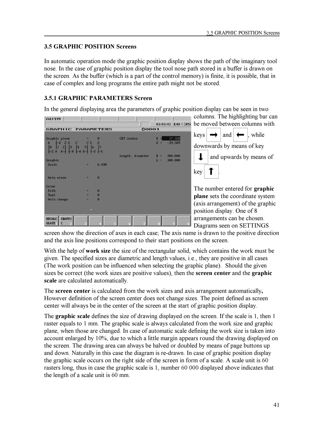
In the general displaying area the parameters of graphic position display can be seen in two columns. The highlighting bar can be moved between columns with
keys ![]() and
and ![]()
![]()
, while
downwards by means of key
key
and upwards by means of
.
The number entered for graphic plane sets the coordinate system (axis arrangement) of the graphic position display. One of 8 arrangements can be chosen. Diagrams seen on SETTINGS
screen show the direction of axes in each case; The axis name is drawn to the positive direction and the axis line positions correspond to their start positions on the screen.
With the help of work size the size of the rectangular solid, which contains the work must be given. The specified sizes are diametric and length values, i.e., they are positive in all cases (The work position can be influenced when selecting the graphic plane). Should the given sizes be correct (the work sizes are positive values), then the screen center and the graphic scale are calculated automatically.
The screen center is calculated from the work sizes and axis arrangement automatically, However definition of the screen center does not change sizes. The point defined as screen center will always be in the center of the screen at the start of graphic position display.
The graphic scale defines the size of drawing displayed on the screen. If the scale is 1, then 1 raster equals to 1 mm. The graphic scale is always calculated from the work size and graphic plane, when those are changed. In case of automatic scale defining the work size is taken into account enlarged by 10%, due to which a little margin appears round the drawing displayed on the screen. The drawing area can always be halved or doubled by means of page buttons up and down. Naturally in this case the diagram is
41