■Connection with the Time-lapse VCR (Panasonic Models)
MUX
1.Configure the parameters of the Multiplexer functions in the Multiplexer Mode (refer to p. 98) window of
Note: To put a file from PC to the unit, select PC in 600 RECORDER in SETUP MENU. (Refer to p. 71.) When VCR is select- ed, parameter configuration in the Multiplexer Mode window is unavailable.
2.After Step 1, select VCR for 600 RECORDER in SETUP MENU. (Refer to p. 71.)
3.Conform the communication speed (SPEED) for 740 CAMERA/DATA 1- 4 PORT in SETUP MENU to that of the
The following parameters are fixed. Data bit: 7 bits
Parity check: ODD
Stop bit: 1 bit
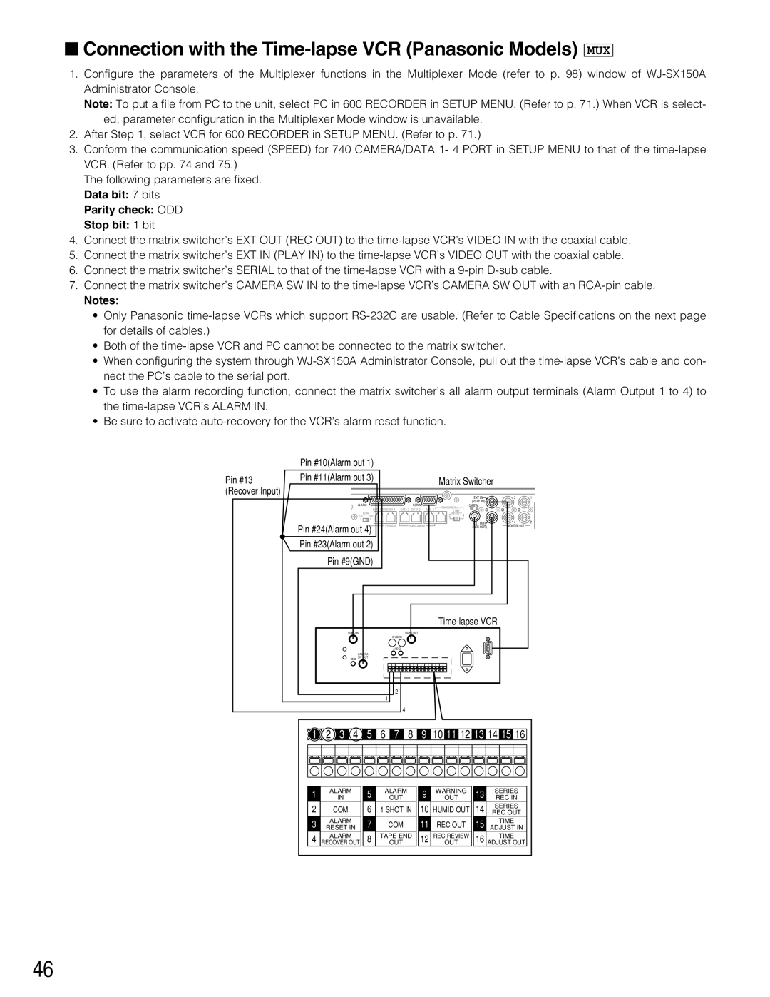
4.Connect the matrix switcher’s EXT OUT (REC OUT) to the
5.Connect the matrix switcher’s EXT IN (PLAY IN) to the
6.Connect the matrix switcher’s SERIAL to that of the
7.Connect the matrix switcher’s CAMERA SW IN to the
Notes:
•Only Panasonic
•Both of the
•When configuring the system through
•To use the alarm recording function, connect the matrix switcher’s all alarm output terminals (Alarm Output 1 to 4) to the
•Be sure to activate
| Pin #10(Alarm out 1) |
|
Pin #13 | Pin #11(Alarm out 3) | Matrix Switcher |
(Recover Input) |
|
|
|
|
|
|
|
|
|
|
|
|
|
|
| EXT IN | 3 | 1 |
|
|
| ALARM |
|
|
| SERIAL |
|
|
|
| (PLAY IN) |
|
| |
|
|
|
|
|
|
| RS485(CAMERA) | CAMERA |
|
| |||||
|
|
|
| DATA HDR DATA 4 | DATA 3 DATA 2 DATA 1 |
| SW IN |
|
| ||||||
|
|
|
|
| LINE |
|
|
| |||||||
|
|
| TERM |
|
|
|
|
|
|
|
|
|
| ||
|
|
|
|
|
|
|
| 2 | SELECT | 4 |
|
|
| ||
|
|
| OFF | ON |
|
|
|
|
|
|
|
|
| ||
Pin #24(Alarm out 4) | PS•DATA | RS485(CAMERA) |
|
|
|
| EXT OUT | 4 | 2 | ||||||
|
|
|
| (REC OUT) | MONITOR OUT |
| |||||||||
|
|
|
|
|
|
|
|
|
|
| |||||
Pin #23(Alarm out 2) |
|
|
|
|
|
|
|
|
|
|
| ||||
| Pin #9(GND) |
|
|
|
|
|
|
|
|
|
|
| |||
|
|
|
|
|
|
|
|
|
|
|
| ||||
|
| VIDEO IN |
|
|
| VIDEO OUT |
|
|
|
|
|
|
|
| |
|
|
|
|
|
|
|
|
|
|
|
|
|
| ||
|
|
|
|
|
| AUDIO |
|
|
|
|
|
|
|
| |
|
|
| CAMERA |
|
|
|
|
|
|
|
|
|
|
| |
|
| GND SW OUT |
|
|
|
|
|
|
|
|
|
|
| ||
|
|
|
|
| 1 | 2 |
|
|
|
|
|
|
|
|
|
|
|
|
|
|
|
|
|
|
|
|
|
|
|
| |
|
|
|
|
|
|
| 4 |
|
|
|
|
|
|
|
|
1 | 2 | 3 | 4 | 5 | 6 | 7 | 8 | 9 | 10 11 12 13 14 15 16 |
| |||||
1 | ALARM |
| 5 | ALARM | 9 |
| WARNING | 13 | SERIES |
| |||||
| IN |
|
| OUT |
| OUT |
| REC IN |
| ||||||
2 |
| COM |
| 6 | 1 SHOT IN | 10 | HUMID OUT | 14 | SERIES |
| |||||
|
| REC OUT |
| ||||||||||||
3 | ALARM |
| 7 |
| COM | 11 |
| REC OUT | 15 | TIME |
| ||||
RESET IN |
|
| ADJUST IN |
| |||||||||||
4 | ALARM |
| 8 | TAPE END | 12 | REC REVIEW | 16 | TIME |
| ||||||
RECOVER OUT |
| OUT |
| OUT |
| ADJUST OUT |
| ||||||||
46