■Connection with the PC
1.Conform the communication speed (SERIAL PORT SPEED) parameter in SETUP MENU to that of the PC.
2.Connect the matrix switcher's serial port to that of the PC with the
or
SERIAL
Personal Computer | Matrix Switcher |
Notes:
•The following parameters are fixed. Data bit: 8 bits
Parity check: none
Stop bit: 1 bit
•Refer to Cable Specifications in this page for details on cables.
●Cable Specifications
PC | Matrix Switcher | ||
1 |
| 1 | |
2 |
| 2 | |
3 |
| 3 | |
4 |
| 4 | |
5 |
| 5 | |
6 |
| 6 | |
7 |
| 7 | |
8 |
| 8 | |
Frame |
|
| Frame |
|
| ||
|
| Shield | |
■Time Adjustment with an External Equipment
The specified external devices can output the time adjust- ing signal to the matrix switcher.
This signal can adjust the time by up to ± 30 seconds every hour.
To use this function, it is necessary to assign the alarm input terminal(s) (pin # 1 to 16) to the time adjusting termi- nal(s).
SETUP MENU or
Note: In the
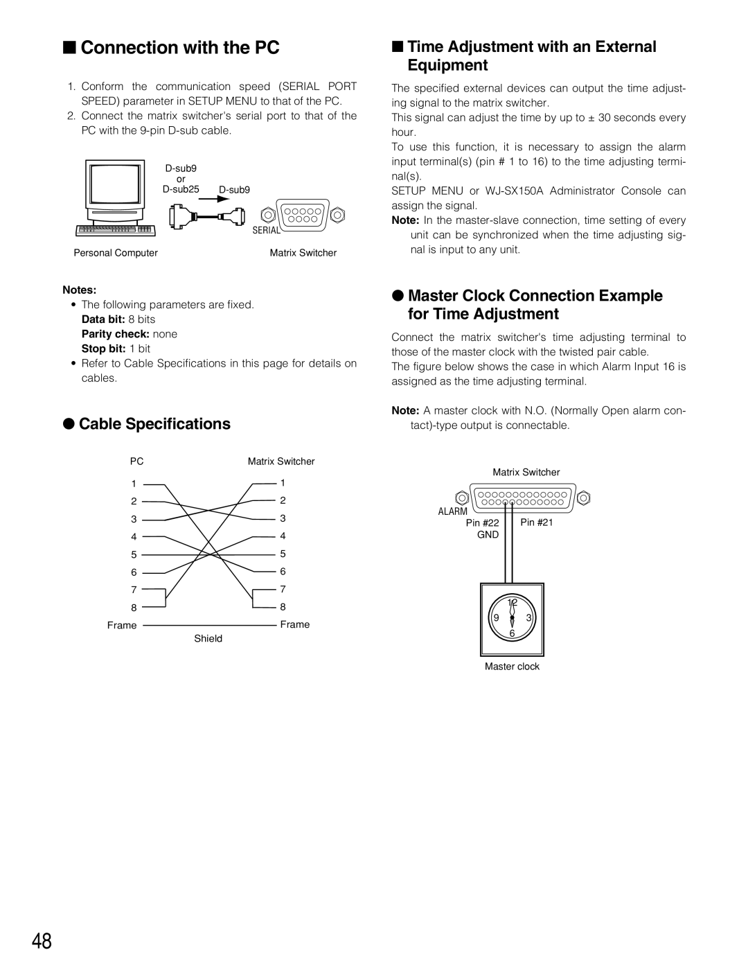
●Master Clock Connection Example for Time Adjustment
Connect the matrix switcher's time adjusting terminal to those of the master clock with the twisted pair cable.
The figure below shows the case in which Alarm Input 16 is assigned as the time adjusting terminal.
Note: A master clock with N.O. (Normally Open alarm con-
Matrix Switcher
ALARM
Pin #22 Pin #21
GND
12
9 ![]() 3
3
6
Master clock
48