■ Connection with the System | ■ Connection with the Alarm |
Controllers | Sensors |
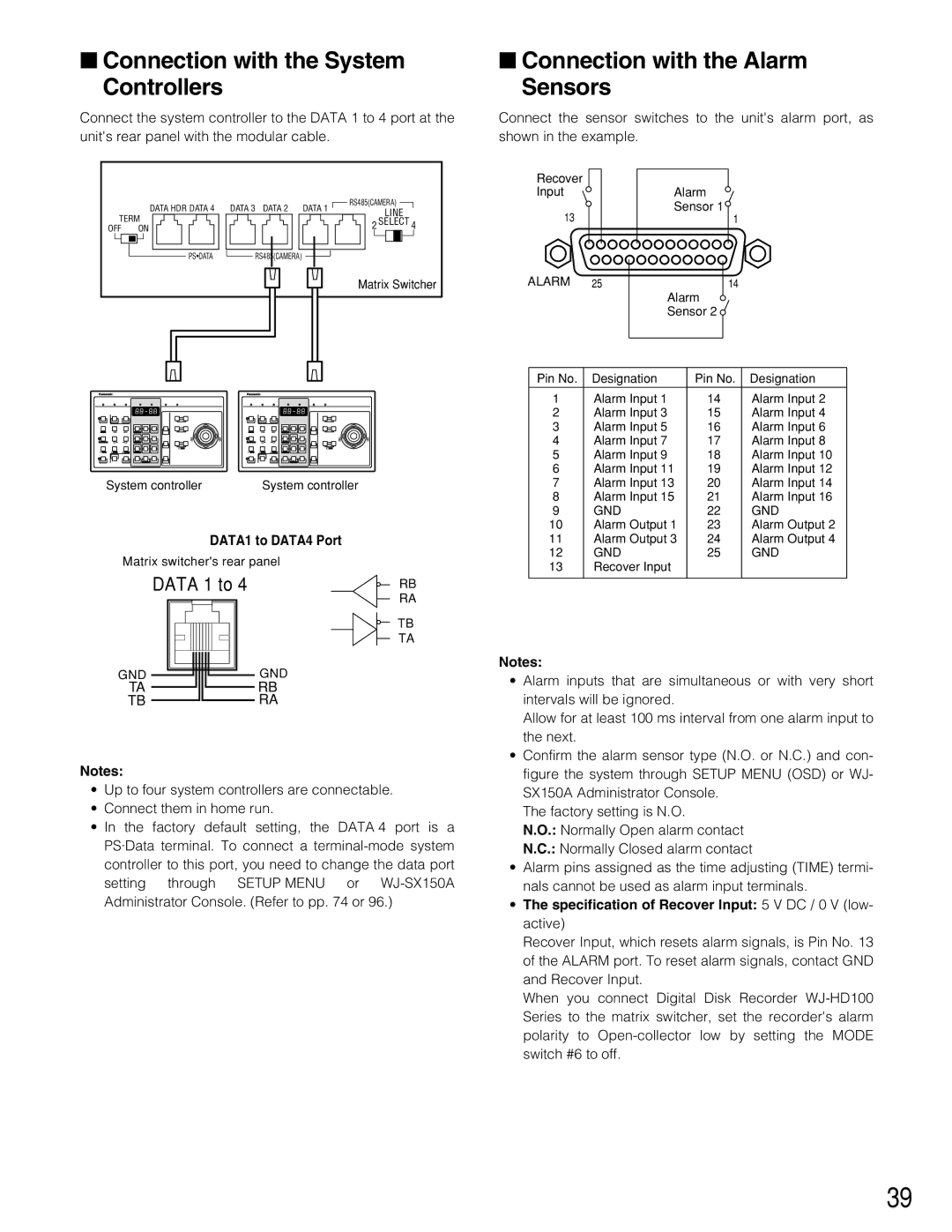
Connect the system controller to the DATA 1 to 4 port at the | Connect the sensor switches to the unit's alarm port, as |
unit's rear panel with the modular cable. | shown in the example. |
| DATA HDR DATA 4 | DATA 3 DATA 2 | DATA 1 | RS485(CAMERA) |
| LINE | |||
TERM |
|
| ||
|
| 2 SELECT 4 | ||
OFF | ON |
|
| |
| PS•DATA | RS485(CAMERA) |
|
|
|
|
|
| Matrix Switcher |
Recover
Input
13
ALARM 25
Alarm ![]() Sensor 1
Sensor 1![]()
1
14
Alarm ![]() Sensor 2
Sensor 2 ![]()
System controllerSystem controller
DATA1 to DATA4 Port
Matrix switcher's rear panel
| DATA 1 to 4 |
|
|
|
| RB | |||||||||||
|
|
|
|
| |||||||||||||
|
|
|
|
|
|
|
|
|
|
|
|
|
|
|
|
| RA |
|
|
|
|
|
|
|
|
|
|
|
|
|
|
|
|
| TB |
|
|
|
|
|
|
|
|
|
|
|
|
|
|
|
|
| TA |
|
|
|
|
|
|
|
|
|
|
|
|
| |||||
GND |
|
|
|
|
|
|
|
|
|
|
|
| GND | ||||
|
|
|
|
|
|
|
|
|
|
|
| ||||||
|
|
|
|
|
|
|
|
|
|
|
| ||||||
|
|
|
|
|
|
|
|
|
|
| |||||||
|
|
|
|
|
|
|
|
|
| ||||||||
|
|
|
|
|
|
|
|
|
|
|
| ||||||
TA |
|
|
|
|
|
|
|
| RB | ||||||||
|
|
|
|
|
|
|
| ||||||||||
TB |
|
|
|
|
|
|
| RA | |||||||||
|
|
|
|
|
|
|
| ||||||||||
Notes:
•Up to four system controllers are connectable.
•Connect them in home run.
•In the factory default setting, the DATA 4 port is a PS·Data terminal. To connect a
Pin No. | Designation |
| Pin No. | Designation |
|
|
|
|
|
|
|
1 | Alarm Input | 1 | 14 | Alarm Input | 2 |
2 | Alarm Input | 3 | 15 | Alarm Input | 4 |
3 | Alarm Input | 5 | 16 | Alarm Input | 6 |
4 | Alarm Input | 7 | 17 | Alarm Input | 8 |
5 | Alarm Input | 9 | 18 | Alarm Input | 10 |
6 | Alarm Input | 11 | 19 | Alarm Input | 12 |
7 | Alarm Input | 13 | 20 | Alarm Input | 14 |
8 | Alarm Input | 15 | 21 | Alarm Input | 16 |
9 | GND |
| 22 | GND |
|
10 | Alarm Output 1 | 23 | Alarm Output 2 | ||
11 | Alarm Output 3 | 24 | Alarm Output 4 | ||
12 | GND |
| 25 | GND |
|
13 | Recover Input |
|
|
| |
|
|
|
|
|
|
Notes:
•Alarm inputs that are simultaneous or with very short intervals will be ignored.
Allow for at least 100 ms interval from one alarm input to the next.
•Confirm the alarm sensor type (N.O. or N.C.) and con- figure the system through SETUP MENU (OSD) or WJ- SX150A Administrator Console.
The factory setting is N.O.
N.O.: Normally Open alarm contact
N.C.: Normally Closed alarm contact
•Alarm pins assigned as the time adjusting (TIME) termi- nals cannot be used as alarm input terminals.
•The specification of Recover Input: 5 V DC / 0 V (low- active)
Recover Input, which resets alarm signals, is Pin No. 13 of the ALARM port. To reset alarm signals, contact GND and Recover Input.
When you connect Digital Disk Recorder
39