When Master, Slave 1 to 3 are connected
CAM | 1 | 2 | 3 | 4 | 5 | 6 | 7 | 8 | 9 | 10 | 11 | 12 | 13 | 14 | 15 | 16 |
|
|
|
|
|
|
|
|
|
|
|
|
|
|
|
|
|
Slave 1 | 1 | 2 | 3 | 4 | 5 | 6 | 7 | 8 | 9 | 10 | 11 | 12 | 13 | 14 | 15 | 16 |
|
|
|
|
|
|
|
|
|
|
|
|
|
|
|
|
|
Slave 2 | 17 | 18 | 19 | 20 | 21 | 22 | 23 | 24 | 25 | 26 | 27 | 28 | 29 | 30 | 31 | 32 |
|
|
|
|
|
|
|
|
|
|
|
|
|
|
|
|
|
Slave 3 | 33 | 34 | 35 | 36 | 37 | 38 | 39 | 40 | 41 | 42 | 43 | 44 | 45 | 46 | 47 | 48 |
|
|
|
|
|
|
|
|
|
|
|
|
|
|
|
|
|
Master | - - | - - | - - | - - | - - | - - | - - | - - | - - | - - | - - | - - | 49 | 50 | 51 | 52 |
|
|
|
|
|
|
|
|
|
|
|
|
|
|
|
|
|
When Master, Slave 1 to 4 are connected | ||||||||||||||||
|
|
|
|
|
|
|
|
|
|
|
|
|
|
|
| |
CAM | 1 | 2 | 3 | 4 | 5 | 6 | 7 | 8 | 9 | 10 | 11 | 12 | 13 | 14 | 15 | 16 |
|
|
|
|
|
|
|
|
|
|
|
|
|
|
|
|
|
Slave 1 | 1 | 2 | 3 | 4 | 5 | 6 | 7 | 8 | 9 | 10 | 11 | 12 | 13 | 14 | 15 | 16 |
|
|
|
|
|
|
|
|
|
|
|
|
|
|
|
|
|
Slave 2 | 17 | 18 | 19 | 20 | 21 | 22 | 23 | 24 | 25 | 26 | 27 | 28 | 29 | 30 | 31 | 32 |
|
|
|
|
|
|
|
|
|
|
|
|
|
|
|
|
|
Slave 3 | 33 | 34 | 35 | 36 | 37 | 38 | 39 | 40 | 41 | 42 | 43 | 44 | 45 | 46 | 47 | 48 |
|
|
|
|
|
|
|
|
|
|
|
|
|
|
|
|
|
Slave 4 | 49 | 50 | 51 | 52 | 53 | 54 | 55 | 56 | 57 | 58 | 59 | 60 | 61 | 62 | 63 | 64 |
|
|
|
|
|
|
|
|
|
|
|
|
|
|
|
|
|
Master | - - | - - | - - | - - | - - | - - | - - | - - | - - | - - | - - | - - | - - | - - | - - | - - |
|
|
|
|
|
|
|
|
|
|
|
|
|
|
|
|
|
Notes:
•When you select logical camera numbers, the setting will be automatically activated in other menus.
•Camera channels of the Master unit which connect Slave units are displayed as a space. You cannot con- figure the parameters.
•You can select a logical camera number for only one channel. When you enter the same number second time, the newer is activated, but the older will be changed to a space.
•COMPENSATION/VD2/DATA
This menu links to the submenu.
Move the cursor and press the CAM (SET) button to go into the menu.
730 COMPENSATION/VD2/DATA will appear on the moni- tor.
730 COMPENSATION/VD2/DATA | 1 of 2 | |||
SWITCHER=SLAVE1(1 of 4) |
| |||
CAM | LCN | COMP | VD2 | DATA |
1 | 1 | S | ON | ON |
2 | 2 | S | ON | ON |
3 | 3 | S | ON | ON |
4 | 4 | S | ON | ON |
5 | 5 | S | ON | ON |
6 | 6 | S | ON | ON |
7 | 7 | S | ON | ON |
8 | 8 | S | ON | ON |
LCN:LOGICAL CAMERA NUMBER
730 COMPENSATION/VD2/DATA | 2 of 2 | |||
SWITCHER=SLAVE1(1 of 4) |
| |||
CAM | LCN | COMP | VD2 | DATA |
9 | 9 | S | ON | ON |
10 | 10 | S | ON | ON |
11 | 11 | S | ON | ON |
12 | 12 | S | ON | ON |
13 | 13 | S | ON | ON |
14 | 14 | S | ON | ON |
15 | 15 | S | ON | ON |
16 | 16 | S | ON | ON |
LCN:LOGICAL CAMERA NUMBER
SWITCHER: Select a unit (SLAVE1 to 4 and MASTER*) to configure the parameters.
*In normal connection, only MASTER is displayed. CAM: This stands for a camera channel of the unit.
LCN: This stands for a logical camera number. 1 to 99 is selectable.
COMP: This stands for cable compensation. Select the desired setting according to the cable length.
S:Less than 400 m (1 300 ft)
M:400 m (1 300 ft) to 700 m (2 300 ft)
L:700 m (2 300 ft) to 900 m (3 000 ft)
Refer to p. 36 for available cables.
The factory default setting is S.
VD2: To send the VD2 timing pulse with the camera output signal, select ON. Not to send the VD2 timing pulse with the camera output signal, select OFF. The factory default setting is ON.
DATA: To send the control data with the camera output sig- nal, select ON. Not to send the control data with the camera output signal, select OFF. The factory default setting is ON.
*The available camera numbers will differ depending on the total number of matrix switchers.
Notes:
•When moving the joystick to ▼ at the bottom of COM- PENSATION/VD2/DATA, the monitor will display 2 of 2.
•When moving the joystick to ▲ at the bottom of COM- PENSATION/VD2/DATA, the monitor will display 1 of 2.
•Camera channels of the Master unit which connect Slave units are displayed as a space. You cannot con- figure the parameters.
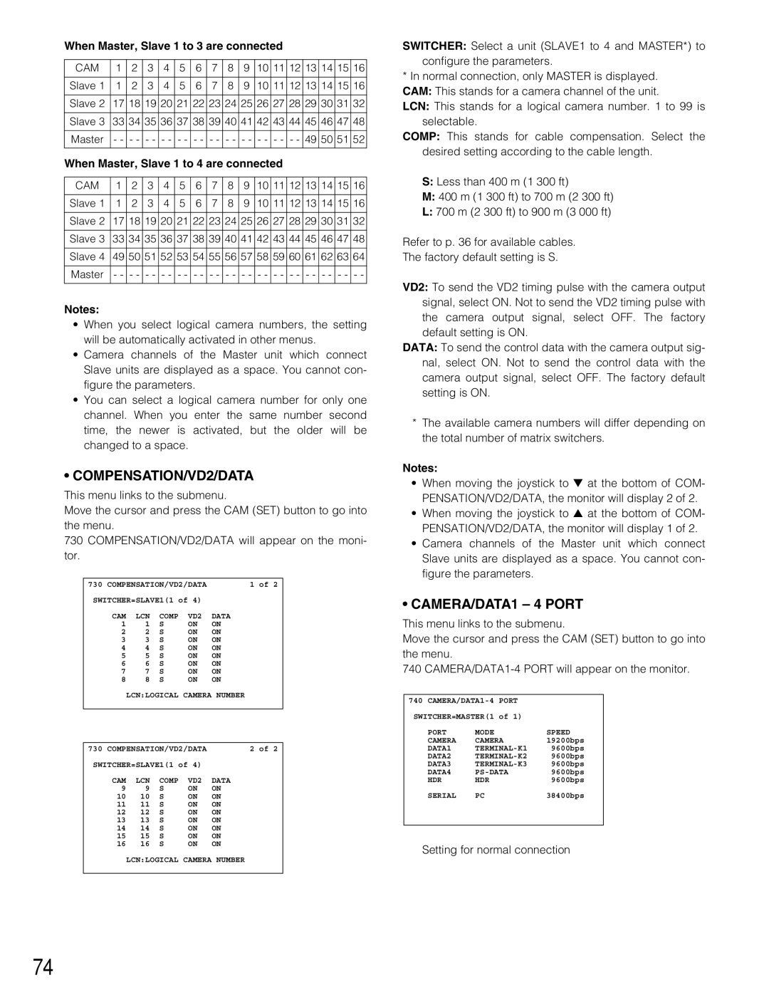
•CAMERA/DATA1 – 4 PORT
This menu links to the submenu.
Move the cursor and press the CAM (SET) button to go into the menu.
740
740
SWITCHER=MASTER(1 of 1)
PORT | MODE | SPEED |
CAMERA | CAMERA | 19200bps |
DATA1 | 9600bps | |
DATA2 | 9600bps | |
DATA3 | 9600bps | |
DATA4 | 9600bps | |
HDR | HDR | 9600bps |
SERIAL | PC | 38400bps |
Setting for normal connection
74