420 ALARM | EVENT |
| 2 | of 10 | ||
ALM MON MODE | REC ALARM PORT |
| ||||
|
| LCN(PRE)/TOUR |
|
|
|
|
11 | 1 | LCN 11 / PRE01 R0 | MASTER / 11 | |||
12 | 1 | LCN 12 / PRE01 R0 | MASTER / 12 | |||
13 | 1 | LCN 13 / PRE01 R0 | MASTER / 13 | |||
14 | 1 | LCN 14 / PRE01 R0 | MASTER / 14 | |||
15 | 1 | LCN 15 / PRE01 R0 | MASTER / 15 | |||
16 | 1 | LCN 16 / PRE01 R0 | MASTER / 16 | |||
17 | 1 | LCN 17 / PRE01 R2 | SLAVE1 / | 1 | ||
18 | 1 | LCN 18 / PRE01 R2 | SLAVE1 / | 2 | ||
19 | 1 | LCN 19 / PRE01 R2 | SLAVE1 / | 3 | ||
20 | 1 | LCN 20 / PRE01 R2 | SLAVE1 / | 4 | ||
|
| LCN:LOGICAL CAMERA | NUMBER |
|
| |
|
|
| ||||
420 ALARM EVENT |
| 10 of 10 | ||||
ALM MON MODE | REC ALARM PORT | |||||
|
| LCN(PRE)/TOUR |
|
|
|
|
91 | 1 | LCN 91 / PRE01 |
|
|
|
|
92 | 1 | LCN 92 / PRE01 |
|
|
|
|
93 | 1 | LCN 93 / PRE01 |
|
|
|
|
94 | 1 | LCN 94 / PRE01 |
|
|
|
|
95 | 1 | LCN 95 / PRE01 |
|
|
|
|
96 | 1 | LCN 96 / PRE01 |
|
|
|
|
97 | 1 | LCN 97 / PRE01 |
|
|
|
|
98 | 1 | LCN 98 / PRE01 |
|
|
|
|
99 | 1 | LCN 99 / PRE01 |
|
|
|
|
LCN:LOGICAL CAMERA NUMBER
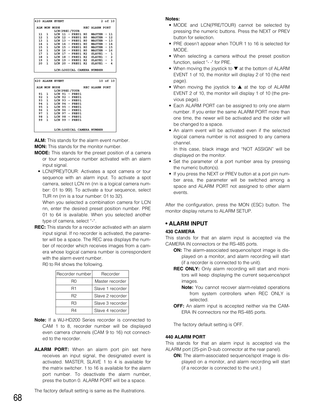
ALM: This stands for the alarm event number.
MON: This stands for the monitor number.
MODE: This stands for the preset position of a camera or tour sequence number activated with an alarm input signal.
•LCN(PRE)/TOUR: Activates a spot camera or tour sequence with an alarm input. To activate a spot camera, select LCN nn (nn is a logical camera num-
ber: 01 to 99). To activate a tour sequence, select
TUR nn (nn is a tour number: 01 to 32).
When you selected a combination camera for LCN nn, enter the desired preset position number. PRE 01 to 64 is available. When you selected another type of camera, select
REC: This stands for a recorder activated with an alarm input signal. If no recorder is activated, the parame- ter will be a space. The REC area displays the num- ber of recorder which receives images from a cam- era whose logical camera number is correspondent with the alarm event number.
R0 to R4 shows the following.
Recorder number | Recorder |
|
|
R0 | Master recorder |
|
|
R1 | Slave 1 recorder |
|
|
R2 | Slave 2 recorder |
|
|
R3 | Slave 3 recorder |
|
|
R4 | Slave 4 recorder |
|
|
Note: If a
ALARM PORT: When an alarm port pin set here receives an input signal, the designated event is activated. MASTER, SLAVE 1 to 4 is available for the matrix switcher. 1 to 16 is available for the alarm port number. To deactivate the alarm number, press the button 0. ALARM PORT will be a space.
The factory default setting is same as the illustrations.
Notes:
•MODE and LCN(PRE/TOUR) cannot be selected by pressing the numeric buttons. Press the NEXT or PREV button for selection.
•PRE doesn’t appear when TOUR 1 to 16 is selected for MODE.
•When selecting a camera without the preset position function, select "-
•When moving the joystick to ▼ at the bottom of ALARM EVENT 1 of 10, the monitor will display 2 of 10 (the next page).
•When moving the joystick to ▲ at the top of ALARM EVENT 2 of 10, the monitor will display 1 of 10 (the pre- vious page).
•Each ALARM PORT can be assigned to only one alarm number. If you enter the same ALARM PORT more than one time, the newer will be activated and the older will be changed to a space.
•An alarm event will be activated even if the selected logical camera number is not assigned to any camera channel.
In this case, black image and “NOT ASSIGN” will be displayed on the monitor.
•Set the parameter of a port number area by pressing the numeric button(s).
•If you press the NEXT or PREV button at a port pin num- ber area, the parameter will be switched among a space and ALARM PORT not assigned to other alarm events.
After the configuration, press the MON (ESC) button. The monitor display returns to ALARM SETUP.
•ALARM INPUT
430 CAMERA
This stands for that an alarm input is accepted via the CAMERA IN connectors or the
ON: The
REC ONLY: Only alarm recording will start and moni- tors will keep displaying the current sequence/spot images.
Note: You cannot recover
OFF: An alarm input is accepted neither via the CAM- ERA IN connectors nor the
The factory default setting is OFF.
440 ALARM PORT
This stands for that an alarm input is accepted via the ALARM port
ON: The
68