CANopen Network Interface
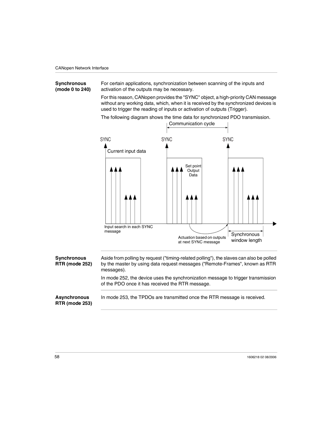
Synchronous For certain applications, synchronization between scanning of the inputs and (mode 0 to 240) activation of the outputs may be necessary.
For this reason, CANopen provides the "SYNC" object, a
The following diagram shows the time data for synchronized PDO transmission. Communication cycle
SYNC | SYNC | SYNC |
Current input data
Set point
Output
Data
Input search in each SYNC message
Actuation based on outputs at next SYNC message
Synchronous window length
Synchronous | Aside from polling by request |
RTR (mode 252) | by the master by using data request messages |
| messages). |
| In mode 252, the device uses the synchronization message to trigger transmission |
| of the PDO once it has received the RTR message. |
Asynchronous |
|
In mode 253, the TPDOs are transmitted once the RTR message is received. | |
RTR (mode 253) |
|
|
|
58 | 1606218 02 08/2006 |
