Software Tools
Steps | Actions |
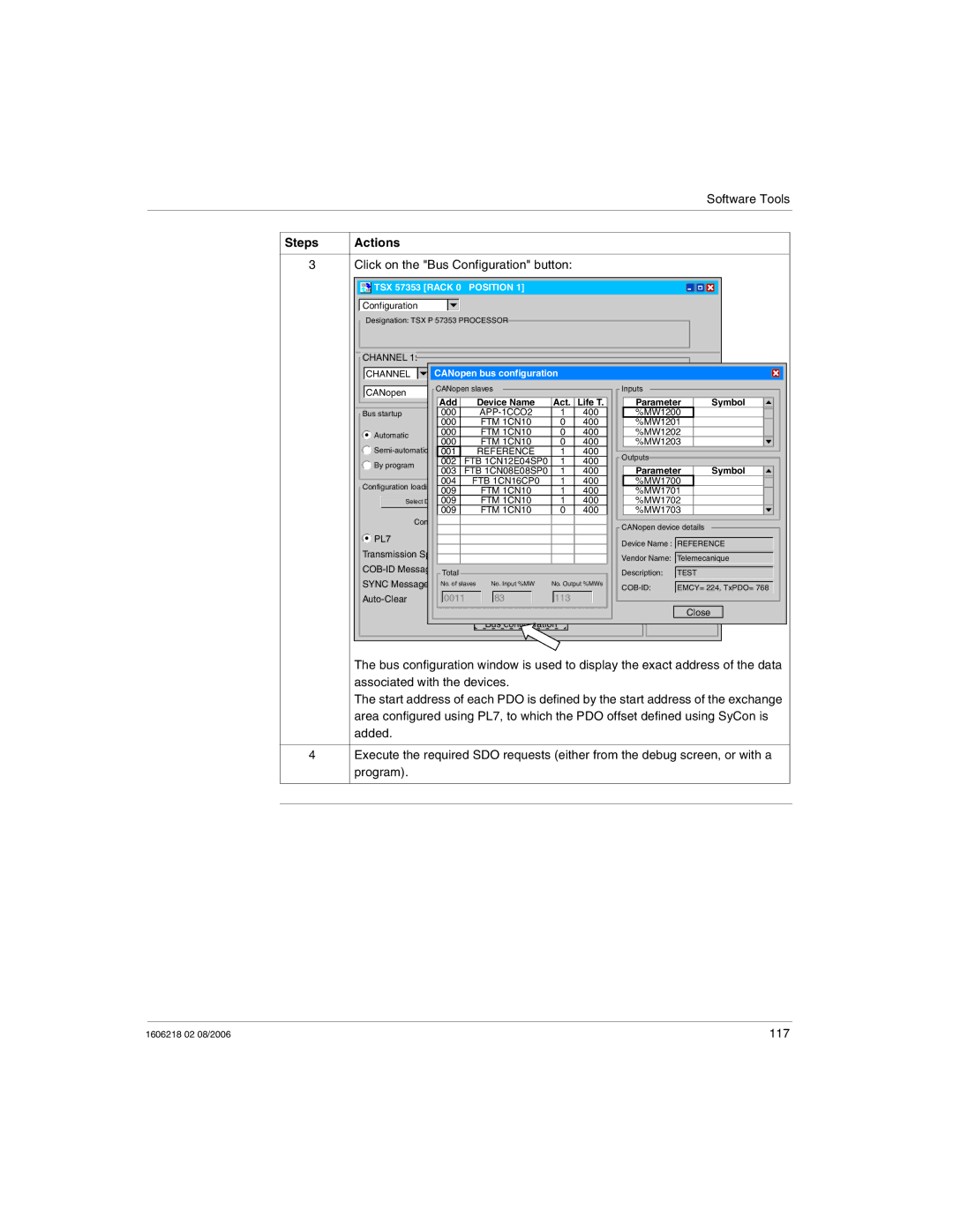
3 | Click on the "Bus Configuration" button: |
TSX 57353 [RACK 0 | POSITION 1] |
Configuration
Designation: TSX P 57353 PROCESSOR
![]() CHANNEL 1:
CHANNEL 1:
CHANNEL 

 CANopen bus configuration
CANopen | CANopen slaves | MAST |
| Inputs |
|
| |||
|
|
|
|
|
|
| |||
| Add | Device Name |
| Act. Life T. |
| Parameter | Symbol | ||
Bus startup | 000 |
| 1 | 400 | Outputs %MW1200 |
| |||
| 000 | FTM 1CN10 |
| 0 | 400 |
| %MW1201 |
| |
Automatic | 000 | FTM 1CN10 |
| 0 | 400 |
| %MW1202 |
| |
000 | FTM 1CN10 |
| 500 | 400 |
| %MW1203 |
| ||
|
|
|
| ||||||
REFERENCE |
| 1 | 400 | No. of words | 500 |
| |||
| 001 |
| Outputs |
|
| ||||
By program | 002 | FTB 1CN12E04SP0 |
| 1000 | 400 |
|
| ||
| Index | Parameter | Symbol | ||||||
003 | FTB 1CN08E08SP0 |
| 1 | 400 | |||||
|
| ||||||||
| 004 | FTB 1CN16CP0 |
| 1 | 400 |
| %MW1700 |
| |
Configuration loading mode | FTM 1CN10 |
| 1 | 400 |
| %MW1701 |
| ||
| 009 |
|
|
| |||||
Select Database009 | FTMD:\document\QSF1CN10 | \CanOpen\trava1 400 il\pro | %MW1702 |
| |||||
| 009 | FTM 1CN10 |
| 0 | 400 |
| %MW1703 |
| |
| Configuration |
|
| CANopen device details | |
|
|
|
| ||
PL7 |
|
| SyConDevice Name : REFERENCE | ||
Transmission Speed |
|
| Vendor Name: Telemecanique | ||
128 |
| SyCon Tool | |||
| Description: | TEST | |||
| Total |
|
| ||
| No. of slaves | No. Input %MW | No. Output %MWs |
|
|
SYNC Message Period | 1000 ms |
| EMCY= 224, TxPDO= 768 | ||
|
|
|
| ||
0011 | 0 83 | 113 |
|
| |
|
|
|
|
| Close |
|
| Bus configuration |
|
| |
The bus configuration window is used to display the exact address of the data associated with the devices.
The start address of each PDO is defined by the start address of the exchange area configured using PL7, to which the PDO offset defined using SyCon is added.
4Execute the required SDO requests (either from the debug screen, or with a program).
1606218 02 08/2006 | 117 |