CANopen Network Interface
![]() CAUTION
CAUTION
Correspondence between
RISK OF EQUIPMENT DAMAGE AND
Unused M12 connectors must not be left unprotected.
If an M12 connector is not fitted with a line terminator or connected to a standard cable, fit a sealing plug so as to guarantee the product’s IP67 protection.
Failure to follow this instruction can result in injury or equipment damage.
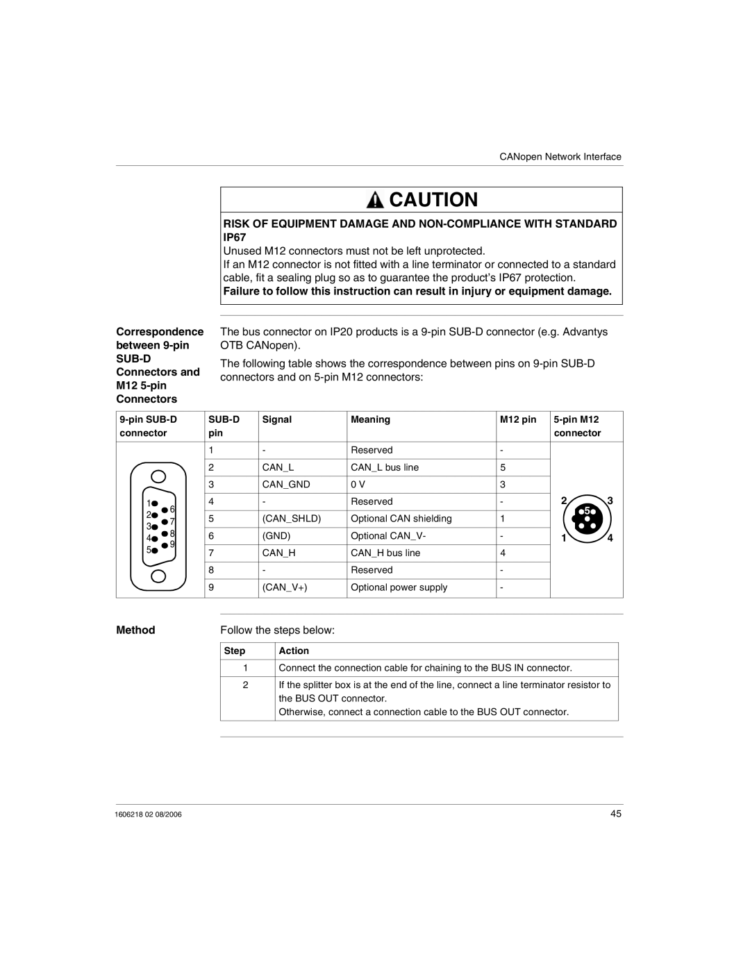
The bus connector on IP20 products is a
The following table shows the correspondence between pins on
|
| Signal | Meaning | M12 pin |
|
| |||
connector |
|
| pin |
|
|
| connector |
| |
|
|
|
|
|
|
|
|
|
|
|
|
| 1 |
| - | Reserved | - |
|
|
|
|
|
|
|
|
|
|
|
|
|
|
| 2 |
| CAN_L | CAN_L bus line | 5 |
|
|
|
|
|
|
|
|
|
|
|
|
|
|
| 3 |
| CAN_GND | 0 V | 3 |
|
|
|
|
|
|
|
|
|
| 2 | 3 |
1 | 6 |
| 4 |
| - | Reserved | - | ||
2 |
|
|
|
|
|
| 5 |
| |
| 5 |
| (CAN_SHLD) | Optional CAN shielding | 1 |
| |||
7 |
|
|
|
| |||||
3 |
|
|
|
| |||||
|
|
|
|
|
|
|
| ||
8 |
| 6 |
| (GND) | Optional CAN_V- | - | 1 | 4 | |
4 |
|
| |||||||
5 | 9 |
|
|
|
|
|
|
|
|
| 7 |
| CAN_H | CAN_H bus line | 4 |
|
| ||
|
|
|
|
| |||||
|
|
|
|
|
| ||||
|
|
|
|
|
|
|
|
|
|
|
|
| 8 |
| - | Reserved | - |
|
|
|
|
|
|
|
|
|
|
|
|
|
|
| 9 |
| (CAN_V+) | Optional power supply | - |
|
|
|
|
|
|
|
|
|
|
|
|
|
|
|
|
|
|
|
|
|
|
Method | Follow the steps below: | ||
|
|
|
|
| Step | Action |
|
|
|
|
|
| 1 | Connect the connection cable for chaining to the BUS IN connector. |
|
|
|
|
|
| 2 | If the splitter box is at the end of the line, connect a line terminator resistor to |
|
|
| the BUS OUT connector. |
|
|
| Otherwise, connect a connection cable to the BUS OUT connector. |
|
|
|
|
|
|
|
|
|
1606218 02 08/2006 | 45 |