CANopen Network Interface
Introduction to Wiring on the CANopen Bus
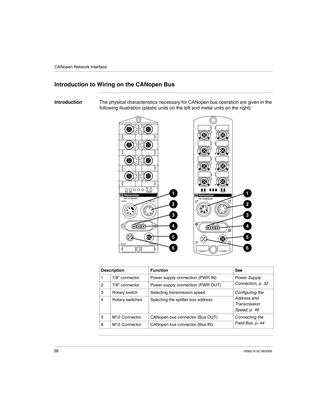
Introduction | The physical characteristics necessary for CANopen bus operation are given in the |
| following illustration (plastic units on the left and metal units on the right): |
|
|
| 1 | 1 |
|
|
| 2 | 2 |
|
|
| 3 | 3 |
|
|
| 4 | 4 |
|
|
| 5 | 5 |
|
|
| 6 | 6 |
|
|
|
|
|
| Description | Function | See | |
|
|
|
|
|
| 1 | 7/8" connector | Power supply connection (PWR IN) | Power Supply |
|
|
|
| Connection, p. 32 |
| 2 | 7/8" connector | Power supply connection (PWR OUT) | |
|
| |||
|
|
|
|
|
| 3 | Rotary switch | Selecting transmission speed | Configuring the |
|
|
|
| Address and |
| 4 | Rotary switches | Selecting the splitter box address | |
| Transmission | |||
|
|
|
| |
|
|
|
| Speed, p. 46 |
|
|
|
|
|
| 5 | M12 Connector | CANopen bus connector (Bus OUT) | Connecting the |
|
|
|
| Field Bus, p. 44 |
| 6 | M12 Connector | CANopen bus connector (Bus IN) | |
|
| |||
|
|
|
|
|
|
|
|
|
|
|
|
|
|
|
38 | 1606218 02 08/2006 |