Diagnostics
Power Supply Diagnostics
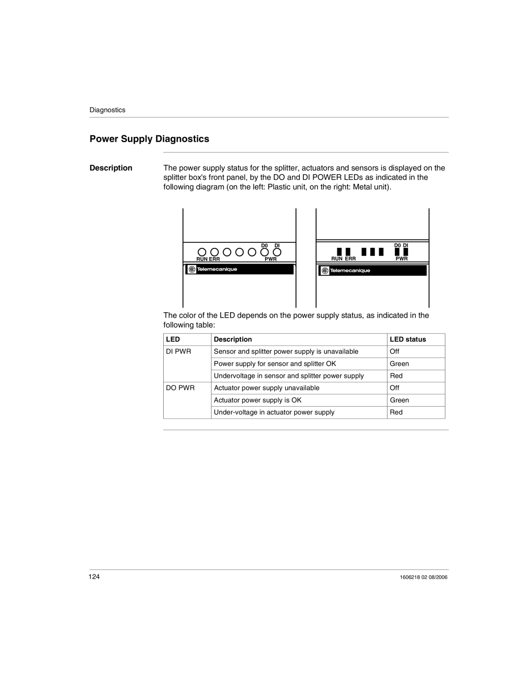
Description | The power supply status for the splitter, actuators and sensors is displayed on the |
| splitter box's front panel, by the DO and DI POWER LEDs as indicated in the |
| following diagram (on the left: Plastic unit, on the right: Metal unit). |
D0 DI
| RUN ERR | PWR |
|
|
|
D0 DI
|
|
|
|
|
|
|
|
|
|
|
|
|
|
|
|
| RUN ERR |
|
|
|
| PWR | |||||||||
|
|
|
|
|
|
|
|
|
|
|
|
|
|
|
|
|
|
|
|
|
|
|
|
|
|
|
|
|
|
|
|
|
|
|
|
|
|
|
|
|
|
|
|
|
|
|
|
The color of the LED depends on the power supply status, as indicated in the following table:
LED | Description | LED status |
|
|
|
|
|
DI PWR | Sensor and splitter power supply is unavailable | Off |
|
|
|
|
|
| Power supply for sensor and splitter OK | Green |
|
|
|
|
|
| Undervoltage in sensor and splitter power supply | Red |
|
|
|
|
|
DO PWR | Actuator power supply unavailable | Off |
|
|
|
|
|
| Actuator power supply is OK | Green |
|
|
|
|
|
| Red |
| |
|
|
|
|
|
|
|
|
124 | 1606218 02 08/2006 |