188
ACK | [ |
|
|
| 1 | L— | |
~ |
|
| |
STROBE ~ |
| ||
| |||
|
| ||
‘“s’ | |||
T: More than 0.5WWC
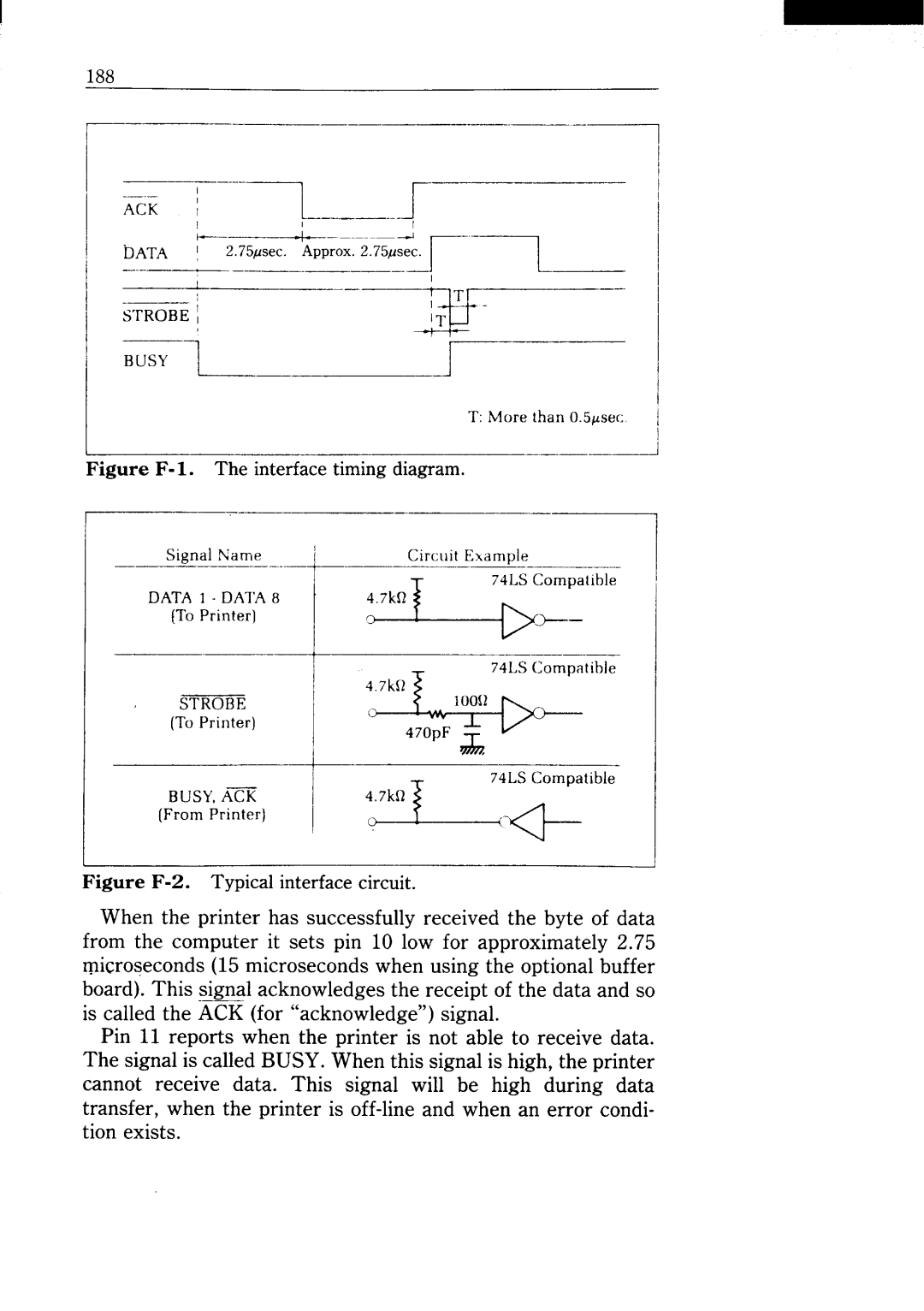
Figure F-1. The interfacetiming diagram.
Siwd N’ame | ! | Circuit Ew3mDle |
|
(To Printer)
STROBE‘sat’’”
BUSY,ACK |
|
(From Printer) | ‘u:~a’ib’e |
|
188
ACK | [ |
|
|
| 1 | L— | |
~ |
|
| |
STROBE ~ |
| ||
| |||
|
| ||
‘“s’ | |||
T: More than 0.5WWC
Siwd N’ame | ! | Circuit Ew3mDle |
|
(To Printer)
STROBE‘sat’’”
BUSY,ACK |
|
(From Printer) | ‘u:~a’ib’e |
|