10. EXTERNAL TERMINAL CONNECTIONS
10.1. RS-232C Terminal Communications Specifications
The Digital Video Recorder can be controlled by a PC or other equipment via a connection through the RS-
232C port. However:
Notes
•Control software is not available as standard accessory.
•TOA takes no responsibility for hardware or software failures or damages resulting from the use of third- party control software.
10.1.1. Communications protocol
Transfer System: Start/stop system
Parity Bit: Even number
Transfer Speed: 9,600 bps, 19,200 bps, and 38,400 bps
Code: Binary code
Bit Length: 8 bits
Flow Control: CTS/RTS handshake or none
Stop Bit: 1
Error Control: None
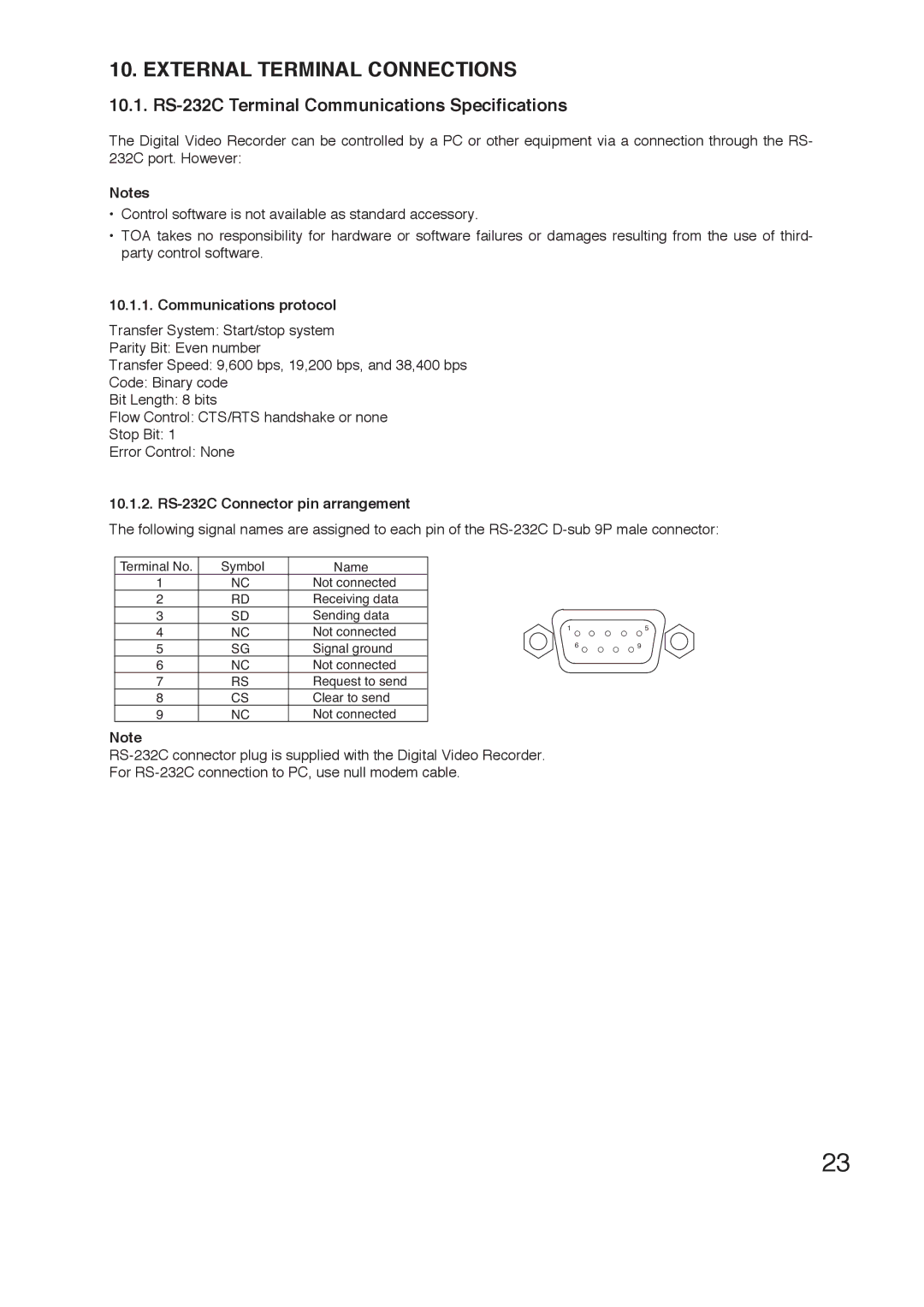
10.1.2. RS-232C Connector pin arrangement
The following signal names are assigned to each pin of the
Terminal No. | Symbol | Name |
1 | NC | Not connected |
2 | RD | Receiving data |
3 | SD | Sending data |
4 | NC | Not connected |
5 | SG | Signal ground |
6 | NC | Not connected |
7 | RS | Request to send |
8 | CS | Clear to send |
9 | NC | Not connected |
Note
15
69
23
