9. CONNECTIONS
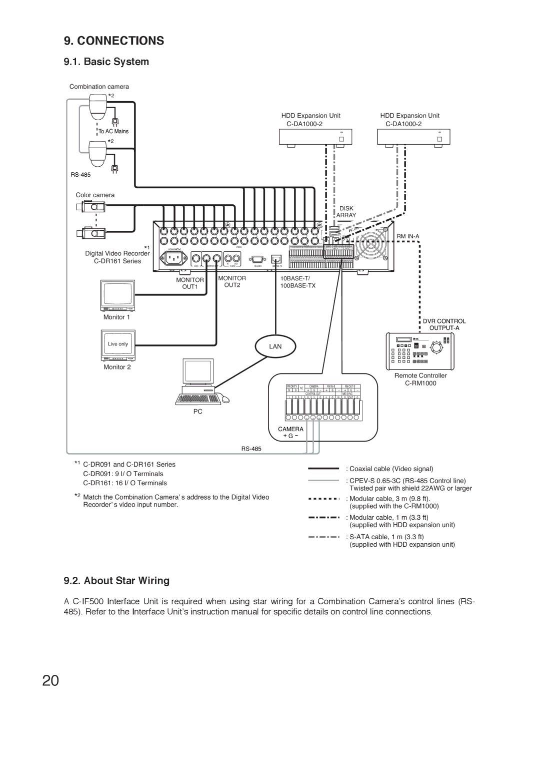
9.1. Basic System
Combination camera
![]()
![]()
![]() *2
*2
![]() To AC Mains
To AC Mains
![]()
![]()
![]()
![]() *2
*2
Color camera
*1
Digital Video Recorder
Monitor 1
Live only
Monitor 2
HDD Expansion Unit | HDD Expansion Unit |
|
|
|
|
|
|
|
|
|
|
|
|
|
|
|
|
|
|
|
|
|
|
| DISK | |||
|
|
|
|
|
|
|
|
|
|
|
|
|
|
|
|
|
|
|
|
|
|
| ||||
|
|
|
|
|
|
|
|
|
|
|
|
|
|
|
|
|
|
|
|
|
|
| ARRAY | |||
|
|
|
|
|
|
|
|
|
|
|
|
|
|
| IN |
|
|
|
|
|
|
|
|
|
|
|
|
|
|
|
|
|
|
|
|
|
|
|
|
|
|
|
|
|
|
|
|
|
|
|
|
| |
1 2 3 4 | 5 | 6 | 7 | 8 9 | 10 11 12 13 |
| 14 |
|
| 15 |
|
|
| 16 |
| 1 |
|
|
|
|
|
|
| RM | RM | |
|
|
|
|
|
|
| DISK ARRAY |
| 2 | |||||||||||||||||
|
|
|
|
|
|
|
|
|
|
|
|
|
|
| OUT |
|
|
|
|
|
|
|
|
|
| |
|
|
|
| VIDEO |
|
|
|
| ALARM IN |
|
|
|
|
| PRIORITY | NC |
| CAMERA | RM | RM |
| |||||
|
|
|
| 1 | G 2 | G 3 | G | 4 | G | 5 | G 6 | G | 7 | G | 8 | G IN |
| G |
| + | G | - + | G | - + G | - | |
AC MAINS |
|
|
|
|
|
|
|
|
|
|
|
|
|
|
|
|
|
|
|
| CONTROL OUT |
| TIME SYNC |
| ||
|
|
|
| 9 | G 10 | G 11 | G | 12 | G | 13 | G 14 | G | 15 | G | 16 | G 1 |
| G | 2 G | 3 | G 4 | G | IN G OUT | G | ||
| 1 | 2 | IN | OUT |
|
|
|
|
|
|
|
|
|
|
|
|
|
|
|
|
|
|
|
|
|
|
LINK | MONITOR OUT |
| AUDIO |
|
|
|
|
|
|
|
|
|
|
|
|
|
|
|
|
|
|
|
|
| ||
MONITOR |
| MONITOR |
|
|
|
|
|
|
|
|
|
|
|
|
|
|
| |||||||||
OUT1 |
|
| OUT2 |
|
|
|
|
|
|
|
|
|
|
|
|
| ||||||||||
DVR CONTROL
LAN
|
|
|
|
| Remote Controller |
PRIORITY | NC | CAMERA | RM | RM | |
| |||||
IN G |
| + G - + G - + G - |
| ||
|
| CONTROL OUT |
| TIME SYNC |
|
1 G | 2 | G 3 G | 4 G IN | G OUT G |
|
PC
CAMERA
+ G -
*1
*2 Match the Combination Camera’ s address to the Digital Video Recorder’ s video input number.
:Coaxial cable (Video signal)
:
:Modular cable, 3 m (9.8 ft). (supplied with the
:Modular cable, 1 m (3.3 ft) (supplied with HDD expansion unit)
:
9.2. About Star Wiring
A
20