Item |
| Selection | Description | ||||
|
|
|
|
|
|
|
|
CONTROLLER |
| 9600 bps / 19200 bps / | Set the Remote controller’s bit rate. | ||||
BIT RATE |
| 38400 bps |
| ||||
|
|
|
|
|
|
|
|
|
|
|
|
|
|
|
|
CONTROLLER |
| ON / OFF | ON: Makes remote controller’s communications responses. *2 | ||||
RESPONSE |
|
|
|
|
|
| OFF: Does not make remote controller’s communications responses. |
|
|
|
|
|
| ||
|
|
|
|
|
|
|
|
1 - 8 |
| Set the Digital Recorder’s ID. *3 | |||||
|
|
|
|
|
|
|
|
LANGUAGE SELECTION | JAPANESE / ENGLISH / FRANCAIS | Select the display language. | |||||
|
|
|
|
|
|
|
|
Note: Underlined settings represent
*1 Changing camera protocols causes the camera transmission speed to change as well. Be sure to match camera settings. *2 If the
will prevent the remote controller from being used.
*3 If a cascading connection is used, be sure that none of the ID numbers are duplicated. It is also possible to use the operation of the Digital Video Recorder to set the
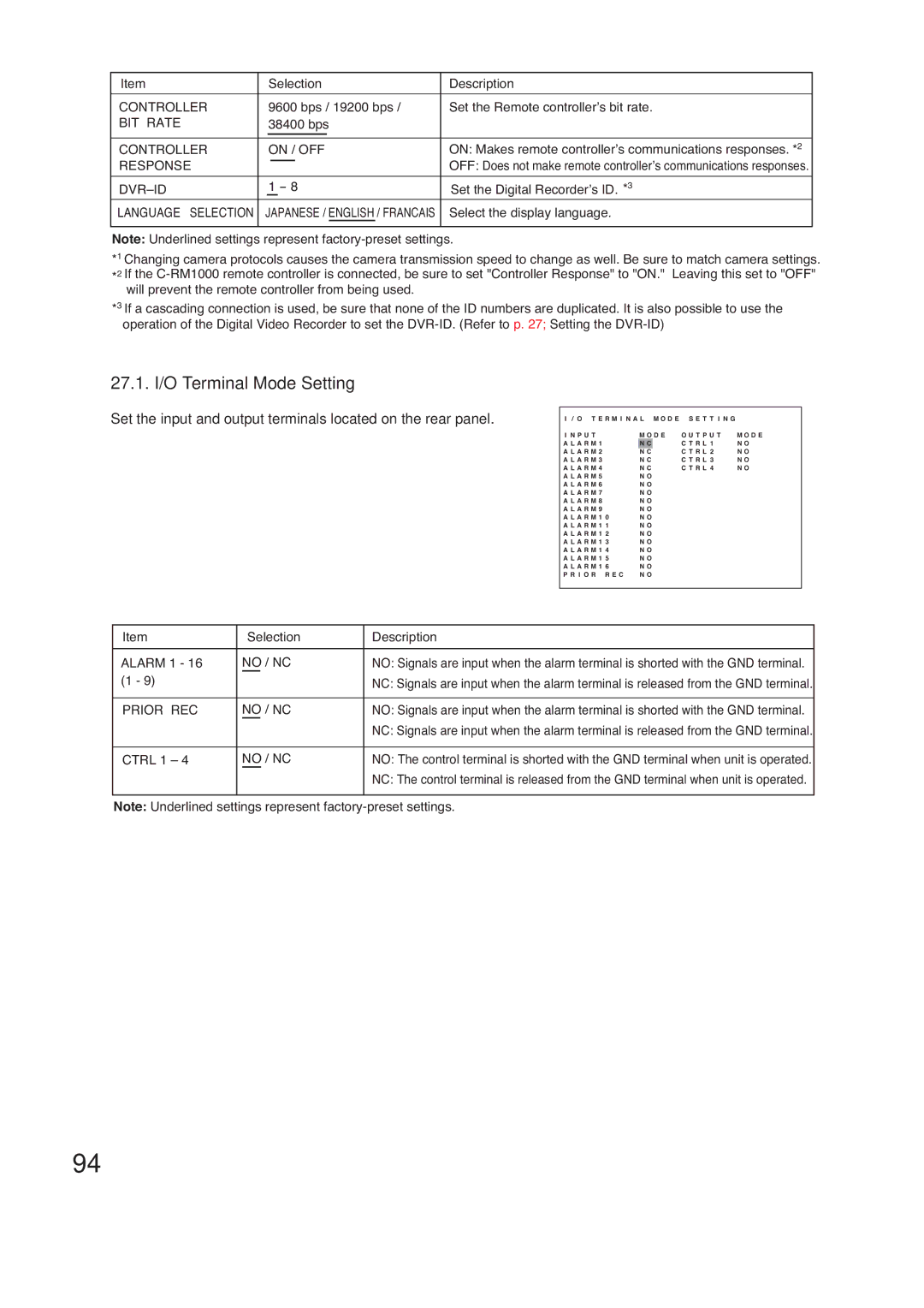
27.1. I/O Terminal Mode Setting
Set the input and output terminals located on the rear panel.
I / O T E R M I N A L M O D E S E T T I N G |
| |||||
I N P U T | M O D E | O U T P U T | M O D E | |||
A L A R M 1 |
|
|
|
| C T R L 1 | N O |
N | C | |||||
A L A R M 2 | N C | C T R L 2 | N O | |||
A L A R M 3 | N C | C T R L 3 | N O | |||
A L A R M 4 | N C | C T R L 4 | N O | |||
A L A R M 5 | N O |
|
| |||
A L A R M 6 | N O |
|
| |||
A L A R M 7 | N O |
|
| |||
A L A R M 8 | N O |
|
| |||
A L A R M 9 | N O |
|
| |||
A L A R M 1 0 | N O |
|
| |||
A L A R M 1 1 | N O |
|
| |||
A L A R M 1 2 | N O |
|
| |||
A L A R M 1 3 | N O |
|
| |||
A L A R M 1 4 | N O |
|
| |||
A L A R M 1 5 | N O |
|
| |||
A L A R M 1 6 | N O |
|
| |||
P R I O R R E C | N O |
|
| |||
Item | Selection | Description |
|
|
|
ALARM 1 - 16 | NO / NC | NO: Signals are input when the alarm terminal is shorted with the GND terminal. |
(1 - 9) |
| NC: Signals are input when the alarm terminal is released from the GND terminal. |
|
|
|
PRIOR REC | NO / NC | NO: Signals are input when the alarm terminal is shorted with the GND terminal. |
| ||
|
| NC: Signals are input when the alarm terminal is released from the GND terminal. |
|
|
|
CTRL 1 – 4 | NO / NC | NO: The control terminal is shorted with the GND terminal when unit is operated. |
|
| NC: The control terminal is released from the GND terminal when unit is operated. |
|
|
|
Note: Underlined settings represent
94