4.14 Base assembly and Cover assembly | 4 Replacement Procedures |
6.Return the display counterclockwise in the original position, close the display and turn over the computer.
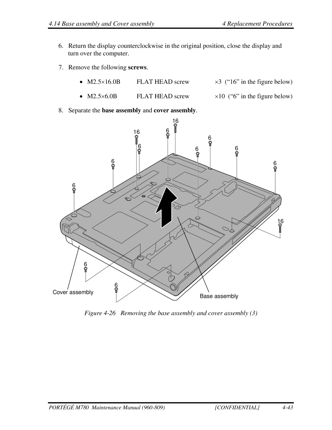
7.Remove the following screws.
∙ | M2.5×16.0B | FLAT HEAD screw | ×3 (“16” in the figure below) |
∙ | M2.5×6.0B | FLAT HEAD screw | ×10 (“6” in the figure below) |
8.Separate the base assembly and cover assembly.
| 16 |
|
16 | 6 | 6 |
|
| |
6 | 6 | 6 |
|
6 | 6 |
|
6
16
6 |
| |
Cover assembly | 6 | |
Base assembly | ||
|
Figure 4-26 Removing the base assembly and cover assembly (3)
PORTÉGÉ M780 Maintenance Manual | [CONFIDENTIAL] |
